LM555
SNAS548C –FEBRUARY 2000–REVISED MARCH 2013
www.ti.com
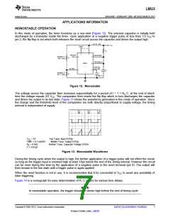
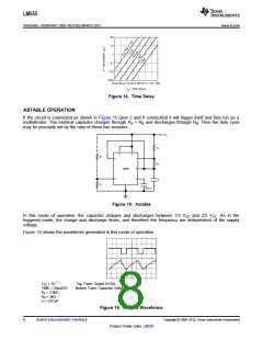
Figure 14. Time Delay
ASTABLE OPERATION
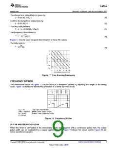
If the circuit is connected as shown in Figure 15 (pins 2 and 6 connected) it will trigger itself and free run as a
multivibrator. The external capacitor charges through RA + RB and discharges through RB. Thus the duty cycle
may be precisely set by the ratio of these two resistors.
Figure 15. Astable
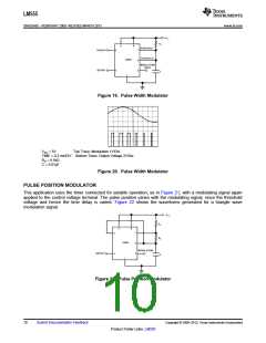
In this mode of operation, the capacitor charges and discharges between 1/3 VCC and 2/3 VCC. As in the
triggered mode, the charge and discharge times, and therefore the frequency are independent of the supply
voltage.
Figure 16 shows the waveforms generated in this mode of operation.
VCC = 5V
Top Trace: Output 5V/Div.
TIME = 20μs/DIV.
RA = 3.9kΩ
RB = 3kΩ
Bottom Trace: Capacitor Voltage 1V/Div.
C = 0.01μF
Figure 16. Astable Waveforms
8
Submit Documentation Feedback
Copyright © 2000–2013, Texas Instruments Incorporated
Product Folder Links: LM555

 TI [ TEXAS INSTRUMENTS ]