LM148-N, LM248-N, LM348-N
www.ti.com
SNOSBT2E –MAY 1999–REVISED MARCH 2013
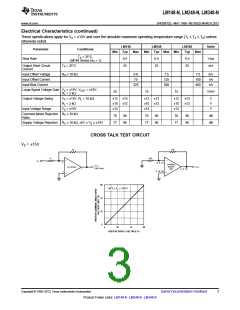
APPLICATION HINTS
The LM148 series are quad low power 741 op amps. In the proliferation of quad op amps, these are the first to
offer the convenience of familiar, easy to use operating characteristics of the 741 op amp. In those applications
where 741 op amps have been employed, the LM148 series op amps can be employed directly with no change
in circuit performance.
The package pin-outs are such that the inverting input of each amplifier is adjacent to its output. In addition, the
amplifier outputs are located in the corners of the package which simplifies PC board layout and minimizes
package related capacitive coupling between amplifiers.
The input characteristics of these amplifiers allow differential input voltages which can exceed the supply
voltages. In addition, if either of the input voltages is within the operating common-mode range, the phase of the
output remains correct. If the negative limit of the operating common-mode range is exceeded at both inputs, the
output voltage will be positive. For input voltages which greatly exceed the maximum supply voltages, either
differentially or common-mode, resistors should be placed in series with the inputs to limit the current.
Like the LM741, these amplifiers can easily drive a 100 pF capacitive load throughout the entire dynamic output
voltage and current range. However, if very large capacitive loads must be driven by a non-inverting unity gain
amplifier, a resistor should be placed between the output (and feedback connection) and the capacitance to
reduce the phase shift resulting from the capacitive loading.
The output current of each amplifier in the package is limited. Short circuits from an output to either ground or the
power supplies will not destroy the unit. However, if multiple output shorts occur simultaneously, the time
duration should be short to prevent the unit from being destroyed as a result of excessive power dissipation in
the IC chip.
As with most amplifiers, care should be taken lead dress, component placement and supply decoupling in order
to ensure stability. For example, resistors from the output to an input should be placed with the body close to the
input to minimize “pickup” and maximize the frequency of the feedback pole which capacitance from the input to
ground creates.
A feedback pole is created when the feedback around any amplifier is resistive. The parallel resistance and
capacitance from the input of the device (usually the inverting input) to AC ground set the frequency of the pole.
In many instances the frequency of this pole is much greater than the expected 3 dB frequency of the closed
loop gain and consequently there is negligible effect on stability margin. However, if the feedback pole is less
than approximately six times the expected 3 dB frequency a lead capacitor should be placed from the output to
the input of the op amp. The value of the added capacitor should be such that the RC time constant of this
capacitor and the resistance it parallels is greater than or equal to the original feedback pole time constant.
Copyright © 1999–2013, Texas Instruments Incorporated
Submit Documentation Feedback
7
Product Folder Links: LM148-N LM248-N LM348-N

 TI [ TEXAS INSTRUMENTS ]