LM134, LM234, LM334
www.ti.com
SNVS746E –MARCH 2000–REVISED MAY 2013
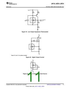
Shunt Capacitance
In certain applications, the 15 pF shunt capacitance of the LM134 may have to be reduced, either because of
loading problems or because it limits the AC output impedance of the current source. This can be easily
accomplished by buffering the LM134 with an FET as shown in the applications. This can reduce capacitance to
less than 3 pF and improve regulation by at least an order of magnitude. DC characteristics (with the exception
of minimum input voltage), are not affected.
Noise
Current noise generated by the LM134 is approximately 4 times the shot noise of a transistor. If the LM134 is
used as an active load for a transistor amplifier, input referred noise will be increased by about 12dB. In many
cases, this is acceptable and a single stage amplifier can be built with a voltage gain exceeding 2000.
Lead Resistance
The sense voltage which determines operating current of the LM134 is less than 100mV. At this level,
thermocouple or lead resistance effects should be minimized by locating the current setting resistor physically
close to the device. Sockets should be avoided if possible. It takes only 0.7Ω contact resistance to reduce output
current by 1% at the 1 mA level.
Sensing Temperature
The LM134 makes an ideal remote temperature sensor because its current mode operation does not lose
accuracy over long wire runs. Output current is directly proportional to absolute temperature in degrees Kelvin,
according to the following formula:
(4)
Calibration of the LM134 is greatly simplified because of the fact that most of the initial inaccuracy is due to a
gain term (slope error) and not an offset. This means that a calibration consisting of a gain adjustment only will
trim both slope and zero at the same time. In addition, gain adjustment is a one point trim because the output of
the LM134 extrapolates to zero at 0°K, independent of RSET or any initial inaccuracy.
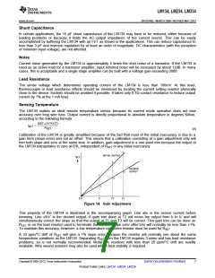
Figure 14. Gain Adjustment
This property of the LM134 is illustrated in the accompanying graph. Line abc is the sensor current before
trimming. Line a′b′c′ is the desired output. A gain trim done at T2 will move the output from b to b′ and will
simultaneously correct the slope so that the output at T1 and T3 will be correct. This gain trim can be done on
RSET or on the load resistor used to terminate the LM134. Slope error after trim will normally be less than ±1%.
To maintain this accuracy, however, a low temperature coefficient resistor must be used for RSET
.
A 33 ppm/°C drift of RSET will give a 1% slope error because the resistor will normally see about the same
temperature variations as the LM134. Separating RSET from the LM134 requires 3 wires and has lead resistance
problems, so is not normally recommended. Metal film resistors with less than 20 ppm/°C drift are readily
available. Wire wound resistors may also be used where best stability is required.
Copyright © 2000–2013, Texas Instruments Incorporated
Submit Documentation Feedback
7
Product Folder Links: LM134 LM234 LM334

 TI [ TEXAS INSTRUMENTS ]