LM120, LM320-N
SNVS756C –APRIL 1998–REVISED APRIL 2013
www.ti.com
These devices have limited built-in ESD protection. The leads should be shorted together or the device placed in conductive foam
during storage or handling to prevent electrostatic damage to the MOS gates.
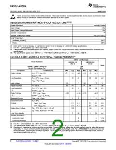
ABSOLUTE MAXIMUM RATINGS−5 VOLT REGULATORS(1)(2)(3)
Power Dissipation
Internally Limited
Input Voltage
−25V
Input-Output Voltage Differential
Junction Temperatures
Storage Temperature Range
Lead Temperature
(Soldering, 10 sec.)
Plastic
25V
(4)
−65°C to +150°C
300°C
260°C
(1) Refer to RETS120-5H drawing for LM120H-5.0 or RETS120-5K drawing for LM120-5K military specifications.
(2) For −5V 3 amp regulators, see LM145 data sheet.
(3) If Military/Aerospace specified devices are required, please contact the Texas Instruments Sales Office/Distributors for availability and
specifications.
(4) This specification applies over −55°C ≤ TJ ≤ +150°C for the LM120 and 0°C ≤ TJ ≤ +125°C for the LM320-N.
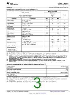
LM120K-5.0 AND LM320K-5.0 ELECTRICAL CHARACTERISTICS(1)
Metal Can Package
Order Numbers
LM120K-5.0
(TO-3)
LM320K-5.0
(TO-3)
Units
Design Output Current (ID)
Device Dissipation (PD)
1.5A
20W
(2)
Parameter
Output Voltage
Conditions
Min
Typ
Max
Min
Typ
Max
TJ = 25°C, VIN =10V,
ILOAD = 5 mA
−5.1
−5
−4.9
−5.2
−5
−4.8
V
Line Regulation
TJ = 25°C, ILOAD = 5 mA,
10
25
10
40
−7
mV
VMIN ≤ VIN ≤ VMAX
Input Voltage
−25
−7
−25
V
Ripple Rejection
f = 120 Hz
54
64
50
54
64
60
dB
mV
Load Regulation,
(3)
TJ = 25°C, VIN = 10V,
5 mA ≤ ILOAD ≤ ID
75
100
Output Voltage,
(2)
−7.5V ≤ VIN ≤ VMAX
5 mA ≤ ILOAD ≤ ID, P ≤ PD
MIN ≤ VIN ≤ VMAX
TJ = 25°C
,
−5.20
−4.80 −5.25
−4.75
V
Quiescent Current
Quiescent Current
Change
V
1
2
1
2
mA
VMIN ≤ VIN ≤ VMAX
0.1
0.1
150
0.4
0.4
0.1
0.1
150
0.4
0.4
mA
mA
μV
5 mA ≤ ILOAD ≤ ID
Output Noise Voltage
TA = 25°C, CL = 1 μF, IL = 5 mA,
VIN = 10V, 10 Hz ≤ f ≤ 100 kHz
Long Term Stability
Thermal Resistance
Junction to Case
5
50
5
50
mV
3
3
°C/W
°C/W
Junction to Ambient
35
35
(1) For −5V 3 amp regulators, see LM145 data sheet.
(2) This specification applies over −55°C ≤ TJ ≤ +150°C for the LM120 and 0°C ≤ TJ ≤ +125°C for the LM320-N.
(3) Regulation is measured at constant junction temperature. Changes in output voltage due to heating effects must be taken into account
separately. To ensure constant junction temperature, low duty cycle, pulse testing is used. The LM120/LM320-N series does have low
thermal feedback, improving line and load regulation. On all other tests, even though power dissipation is internally limited, electrical
specifications apply only up to PD.
2
Submit Documentation Feedback
Copyright © 1998–2013, Texas Instruments Incorporated
Product Folder Links: LM120 LM320-N

 TI [ TEXAS INSTRUMENTS ]