LM2940-N, LM2940C
SNVS769I –MARCH 2000–REVISED APRIL 2013
www.ti.com
APPLICATION INFORMATION
EXTERNAL CAPACITORS
The output capacitor is critical to maintaining regulator stability, and must meet the required conditions for both
ESR (Equivalent Series Resistance) and minimum amount of capacitance.
MINIMUM CAPACITANCE:
The minimum output capacitance required to maintain stability is 22 μF (this value may be increased without
limit). Larger values of output capacitance will give improved transient response.
ESR LIMITS:
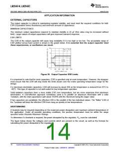
The ESR of the output capacitor will cause loop instability if it is too high or too low. The acceptable range of
ESR plotted versus load current is shown in the graph below. It is essential that the output capacitor meet
these requirements, or oscillations can result.
Figure 35. Output Capacitor ESR Limits
It is important to note that for most capacitors, ESR is specified only at room temperature. However, the designer
must ensure that the ESR will stay inside the limits shown over the entire operating temperature range for the
design.
For aluminum electrolytic capacitors, ESR will increase by about 30X as the temperature is reduced from 25°C to
−40°C. This type of capacitor is not well-suited for low temperature operation.
Solid tantalum capacitors have a more stable ESR over temperature, but are more expensive than aluminum
electrolytics. A cost-effective approach sometimes used is to parallel an aluminum electrolytic with a solid
Tantalum, with the total capacitance split about 75/25% with the Aluminum being the larger value.
If two capacitors are paralleled, the effective ESR is the parallel of the two individual values. The “flatter” ESR of
the Tantalum will keep the effective ESR from rising as quickly at low temperatures.
HEATSINKING
A heatsink may be required depending on the maximum power dissipation and maximum ambient temperature of
the application. Under all possible operating conditions, the junction temperature must be within the range
specified under Absolute Maximum Ratings.
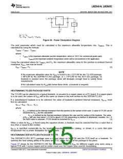
To determine if a heatsink is required, the power dissipated by the regulator, PD, must be calculated.
The figure below shows the voltages and currents which are present in the circuit, as well as the formula for
calculating the power dissipated in the regulator:
14
Submit Documentation Feedback
Copyright © 2000–2013, Texas Instruments Incorporated
Product Folder Links: LM2940-N LM2940C

 TI [ TEXAS INSTRUMENTS ]