LM2940-N, LM2940C
www.ti.com
SNVS769I –MARCH 2000–REVISED APRIL 2013
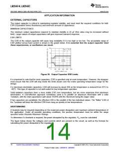
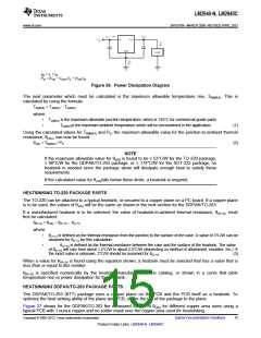
IIN = IL + IG
PD = (VIN − VOUT) IL + (VIN) IG
Figure 36. Power Dissipation Diagram
The next parameter which must be calculated is the maximum allowable temperature rise, TR(MAX). This is
calculated by using the formula:
TR(MAX) = TJ(MAX) − TA(MAX)
where
•
•
TJ(MAX) is the maximum allowable junction temperature, which is 125°C for commercial grade parts.
TA(MAX)is the maximum ambient temperature which will be encountered in the application.
(1)
Using the calculated values for TR(MAX) and PD, the maximum allowable value for the junction-to-ambient thermal
resistance, θ(JA), can now be found:
θ(JA) = TR(MAX) / PD
(2)
NOTE
If the maximum allowable value for θ(JA) is found to be ≥ 53°C/W for the TO-220 package,
≥ 80°C/W for the DDPAK/TO-263 package, or ≥ 174°C/W for the SOT-223 package, no
heatsink is needed since the package alone will dissipate enough heat to satisfy these
requirements.
If the calculated value for θ(JA)falls below these limits, a heatsink is required.
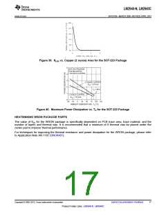
HEATSINKING TO-220 PACKAGE PARTS
The TO-220 can be attached to a typical heatsink, or secured to a copper plane on a PC board. If a copper plane
is to be used, the values of θ(JA) will be the same as shown in the next section for the DDPAK/TO-263.
If a manufactured heatsink is to be selected, the value of heatsink-to-ambient thermal resistance, θ(H−A), must
first be calculated:
θ(H−A) = θ(JA) − θ(C−H) − θ(J−C)
where
•
θ(J−C) is defined as the thermal resistance from the junction to the surface of the case. A value of 3°C/W can be
assumed for θ(J−C) for this calculation.
•
θ(C−H) is defined as the thermal resistance between the case and the surface of the heatsink. The value
of θ(C−H) will vary from about 1.5°C/W to about 2.5°C/W (depending on method of attachment, insulator, etc.). If
the exact value is unknown, 2°C/W should be assumed for θ(C−H)
.
(3)
When a value for θ(H−A) is found using the equation shown, a heatsink must be selected that has a value that is
less than or equal to this number.
θ(H−A) is specified numerically by the heatsink manufacturer in the catalog, or shown in a curve that plots
temperature rise vs power dissipation for the heatsink.
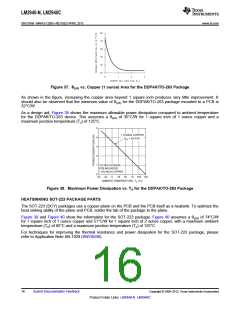
HEATSINKING DDPAK/TO-263 PACKAGE PARTS
The DDPAK/TO-263 (KTT) package uses a copper plane on the PCB and the PCB itself as a heatsink. To
optimize the heat sinking ability of the plane and PCB, solder the tab of the package to the plane.
Figure 37 shows for the DDPAK/TO-263 the measured values of θ(JA) for different copper area sizes using a
typical PCB with 1 ounce copper and no solder mask over the copper area used for heatsinking.
Copyright © 2000–2013, Texas Instruments Incorporated
Submit Documentation Feedback
15
Product Folder Links: LM2940-N LM2940C

 TI [ TEXAS INSTRUMENTS ]