LM1881
www.ti.com
SNLS384F –FEBRUARY 1995–REVISED MARCH 2013
pulse the integrator output should be between V1 and V2. This would give a high level at the output of the
comparator with V1 as one of its inputs. This high is clocked into the “D” flip-flop by the falling edge of the
serration pulse (remember the sync signal is inverted in this section of the LM1881). The “Q” output of the “D”
flip-flop goes through the OR gate, and sets the R/S flip-flop. The output of the R/S flip-flop enables the internal
oscillator and also clocks the ODD/EVEN “D” flip-flop. The ODD/EVEN field pulse operation is covered in the
next section. The output of the oscillator goes to a divide by 8 circuit, thus resetting the R/S flip-flop after 8 cycles
of the oscillator. The frequency of the oscillator is established by the internal capacitor going to the oscillator and
the external RSET. The “Q” output of the R/S flip-flop goes to pin 3 and is the actual vertical sync output of the
LM1881. By clocking the “D” flip-flop at the start of the first serration pulse means that the vertical sync output
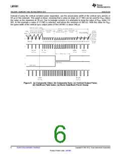
pulse starts at this point in time and lasts for eight cycles of the internal oscillator as shown in Figure 8.
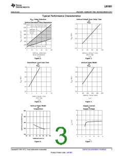
How RSET affects the integrator and the internal oscillator is shown under the Typical Performance
Characteristics. The first graph is “RSET Value Selection vs Vertical Serration Pulse Separation”. For this graph to
be valid, the vertical sync pulse should last for at least 85% of the horizontal half line (47% of a full horizontal
line). A vertical sync pulse from any standard should meet this requirement; both NTSC and PAL do meet this
requirement (the serration pulse is the remainder of the period, 10% to 15% of the horizontal half line).
Remember this pulse is a positive pulse at the integrator but negative in Figure 8. This graph shows how long it
takes the integrator to charge its internal capacitor above V1.
With RSET too large the charging current of the integrator will be too small to charge the capacitor above V1, thus
there will be no vertical synch output pulse. As mentioned above, RSET also sets the frequency of the internal
oscillator. If the oscillator runs too fast its eight cycles will be shorter than the vertical sync portion of the
composite sync. Under this condition another vertical sync pulse can be generated on one of the later serration
pulse after the divide by 8 circuit resets the R/S flip-flop. The first graph also shows the minimum RSET necessary
to prevent a double vertical pulse, assuming that the serration pulses last for only three full horizontal line periods
(six serration pulses for NTSC). The actual pulse width of the vertical sync pulse is shown in the “Vertical Pulse
Width vs RSET” graph. Using NTSC as an example, lets see how these two graphs relate to each other. The
Horizontal line is 64 µs long, or 32 µs for a horizontal half line. Now round this off to 30 µs. In the “RSET Value
Selection vs Vertical Serration Pulse Separation” graph the minimum resistor value for 30 µs serration pulse
separation is about 550 kΩ. Going to the “Vertical Pulse Width vs RSET” graph one can see that 550 kΩ gives a
vertical pulse width of about 180 µs, the total time for the vertical sync period of NTSC (3 horizontal lines). A 550
kΩ will set the internal oscillator to a frequency such that eight cycles gives a time of 180 µs, just long enough to
prevent a double vertical sync pulse at the vertical sync output of the LM1881.
The LM1881 also generates a default vertical sync pulse when the vertical sync period is unusually long and has
no serration pulses. With a very long vertical sync time the integrator has time to charge its internal capacitor
above the voltage level V2. Since there is no falling edge at the end of a serration pulse to clock the “D” flip-flop,
the only high signal going to the OR gate is from the default comparator when output of the integrator reaches
V2. At this time the R/S flip-flop is toggled by the default comparator, starting the vertical sync pulse at pin 3 of
the LM1881. If the default vertical sync period ends before the end of the input vertical sync period, then the
falling edge of the vertical sync (positive pulse at the “D” flip-flop) will clock the high output from the comparator
with V1 as a reference input. This will retrigger the oscillator, generating a second vertical sync output pulse. The
“Vertical Default Sync Delay Time vs RSET” graph shows the relationship between the RSET value and the delay
time from the start of the vertical sync period before the default vertical sync pulse is generated. Using the NTSC
example again the smallest resistor for RSET is 500 kΩ. The vertical default time delay is about 50 µs, much
longer than the 30 µs serration pulse spacing.
A common question is how can one calculate the required RSET with a video timing standard that has no
serration pulses during the vertical blanking. If the default vertical sync is to be used this is a very easy task. Use
the “Vertical Default Sync Delay Time vs RSET” graph to select the necessary RSET to give the desired delay time
for the vertical sync output signal. If a second pulse is undesirable, then check the “Vertical Pulse Width vs RSET
”
graph to make sure the vertical output pulse will extend beyond the end of the input vertical sync period. In most
systems the end of the vertical sync period may be very accurate. In this case the preferred design may be to
start the vertical sync pulse at the end of the vertical sync period, similar to starting the vertical sync pulse after
the first serration pulse. A VGA standard is to be used as an example to show how this is done. In this standard
a horizontal line is 32 µs long. The vertical sync period is two horizontal lines long, or 64 µs. The vertical default
sync delay time must be longer than the vertical sync period of 64 µs. In this case RSET must be larger than 680
kΩ. RSET must still be small enough for the output of the integrator to reach V1 before the end of the vertical
period of the input pulse. The first graph can be used to confirm that RSET is small enough for the integrator.
Copyright © 1995–2013, Texas Instruments Incorporated
Submit Documentation Feedback
5
Product Folder Links: LM1881

 TI [ TEXAS INSTRUMENTS ]