LF155, LF156, LF355, LF356, LF357
www.ti.com
SNOSBH0C –MAY 2000–REVISED MARCH 2013
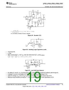
R1, R4 matched. Linearity 0.1% over 2 decades.
Figure 49. Decades VCO
Figure 50. Isolating Large Capacitive Loads
•
•
•
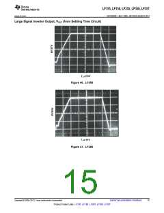
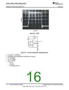
Overshoot 6%
ts 10μs
When driving large CL, the VOUT slew rate determined by CL and IOUT(MAX)
:
Figure 51. Low Drift Peak Detector
•
•
•
•
By adding D1 and Rf, VD1=0 during hold mode. Leakage of D2 provided by feedback path through Rf.
Leakage of circuit is essentially Ib (LF155, LF156) plus capacitor leakage of Cp.
Diode D3 clamps VOUT (A1) to VIN−VD3 to improve speed and to limit reverse bias of D2.
Maximum input frequency should be << ½πRfCD2 where CD2 is the shunt capacitance of D2.
Copyright © 2000–2013, Texas Instruments Incorporated
Submit Documentation Feedback
19
Product Folder Links: LF155 LF156 LF355 LF356 LF357

 TI [ TEXAS INSTRUMENTS ]