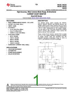
INA282, INA283
INA284, INA285
INA286
SBOS485A –NOVEMBER 2009–REVISED JULY 2010
www.ti.com
This integrated circuit can be damaged by ESD. Texas Instruments recommends that all integrated circuits be handled with
appropriate precautions. Failure to observe proper handling and installation procedures can cause damage.
ESD damage can range from subtle performance degradation to complete device failure. Precision integrated circuits may be more
susceptible to damage because very small parametric changes could cause the device not to meet its published specifications.
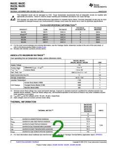
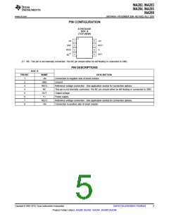
PACKAGE/ORDERING INFORMATION(1)
PACKAGE
DESIGNATOR
PACKAGE
MARKING
PRODUCT
INA282
INA283(2)
GAIN
50V/V
PACKAGE
SOIC-8
SOIC-8
SOIC-8
SOIC-8
SOIC-8
D
D
D
D
D
I282A
I283A
I284A
I285A
I286A
200V/V
500V/V
1000V/V
100V/V
INA284
INA285
INA286
(1) For the most current package and ordering information, see the Package Option Addendum located at the end of this data sheet, or
refer to the device product folder at www.ti.com.
(2) Shaded cells indicate a product preview device.
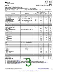
ABSOLUTE MAXIMUM RATINGS(1)
Over operating free-air temperature range, unless otherwise noted.
INA282, INA283,
INA284, INA285, INA286
UNIT
V
Supply Voltage
Analog Inputs,
+18
(3)
Differential (V+IN) – (V–IN
)
–5 to +5
V
(2)
V+IN, V–IN
Common-Mode
–14 to +80
V
Ref1, Ref2, Out
GND–0.3 to (V+) + 0.3
V
Input Current into Any Pin
Storage Temperature
Junction Temperature
5
–65 to +150
+150
mA
°C
°C
V
Human Body Model (HBM)
Charged-Device Model (CDM)
Machine Model (MM)
3000
ESD Ratings:
1000
V
200
V
(1) Stresses above these ratings may cause permanent damage. Exposure to absolute maximum conditions for extended periods may
degrade device reliability. These are stress ratings only, and functional operation of the device at these or any other conditions beyond
those specified is not implied.
(2) V+IN and V–IN are the voltages at the +IN and –IN pins, respectively.
(3) Input voltages must not exceed common-mode rating.
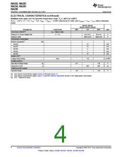
THERMAL INFORMATION
INA282AID,
INA283AID,
INA284AID,
INA285AID,
THERMAL METRIC(1)
UNITS
INA286AID
D
8
qJA
Junction-to-ambient thermal resistance
134.9
72.9
61.3
18.9
54.3
n/a
qJCtop
qJB
Junction-to-case (top) thermal resistance
Junction-to-board thermal resistance
°C/W
yJT
Junction-to-top characterization parameter
Junction-to-board characterization parameter
Junction-to-case (bottom) thermal resistance
yJB
qJCbot
(1) For more information about traditional and new thermal metrics, see the IC Package Thermal Metrics application report, SPRA953.
2
Submit Documentation Feedback
Copyright © 2009–2010, Texas Instruments Incorporated
Product Folder Link(s): INA282 INA283 INA284 INA285 INA286

 TI [ TEXAS INSTRUMENTS ]