DM385, DM388
SPRS821D –MARCH 2013–REVISED DECEMBER 2013
www.ti.com
8.19.2 UART Electrical/Data Timing
Table 8-83. Timing Requirements for UART
(see Figure 8-94)
OPP100/OPP120/
Turbo/Nitro
NO.
UNIT
MIN
0.96U(1)
0.96U(1)
P(2)
MAX
1.05U(1)
1.05U(1)
4
5
tw(RX)
Pulse width, receive data bit, 15/30/100pF high or low
Pulse width, receive start bit, 15/30/100pF high or low
Delay time, transmit start bit to transmit data
ns
ns
ns
ns
tw(CTS)
td(RTS-TX)
td(CTS-TX)
Delay time, receive start bit to transmit data
P(2)
(1) U = UART baud time = 1/programmed baud rate
(2) P = Clock period of the reference clock (FCLK, usually 48 MHz).
Table 8-84. Switching Characteristics Over Recommended Operating Conditions for UART
(see Figure 8-94)
OPP100/OPP120/
Turbo/Nitro
NO.
PARAMETER
UNIT
MIN
MAX
15 pF
30 pF
100 pF
5
0.23
f(baud)
Maximum programmable baud rate
MHz
0.115
2
3
tw(TX)
Pulse width, transmit data bit, 15/30/100 pF high or low
Pulse width, transmit start bit, 15/30/100 pF high or low
U - 2(1)
U - 2(1)
U + 2(1)
U + 2(1)
ns
ns
tw(RTS)
(1) U = UART baud time = 1/programmed baud rate
3
2
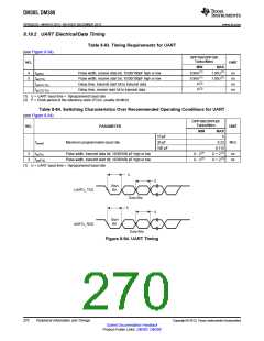
Start
Bit
UARTx_TXD
Data Bits
5
4
Start
Bit
UARTx_RXD
Data Bits
Figure 8-94. UART Timing
270
Peripheral Information and Timings
Copyright © 2013, Texas Instruments Incorporated
Submit Documentation Feedback
Product Folder Links: DM385 DM388

 TI [ TEXAS INSTRUMENTS ]