DM385, DM388
SPRS821D –MARCH 2013–REVISED DECEMBER 2013
www.ti.com
Table 8-60. Supported DDR3 Device Combinations
NUMBER OF DDR3 DEVICES
DDR3 DEVICE WIDTH (BITS)
MIRRORED?
DDR3 EMIF WIDTH (BITS)
1
2
2
2
4
4
16
8
N
Y(1)
N
16
16
32
32
32
32
16
16
8
Y(1)
N
Y(2)
8
(1) Two DDR3 devices are mirrored when one device is placed on the top of the board and the second device is placed on the bottom of
the board.
(2) This is two mirrored pairs of DDR3 devices.
8.13.3.3 DDR3 Interface Schematic
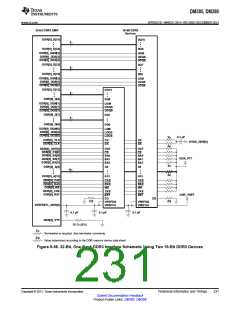
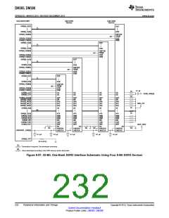
8.13.3.3.1 32-Bit DDR3 Interface
The DDR3 interface schematic varies, depending upon the width of the DDR3 devices used and the width
of the bus used (16 or 32 bits). General connectivity is straightforward and very similar. 16-bit DDR
devices look like two 8-bit devices. Figure 8-56 and Figure 8-57 show the schematic connections for 32-bit
interfaces using x16 devices.
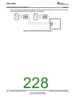
8.13.3.3.2 16-Bit DDR3 Interface
Note that the 16-bit wide interface schematic is practically identical to the 32-bit interface (see Figure 8-56
and Figure 8-57); only the high-word DDR memories are removed and the unused DQS inputs are tied off.
The processor DDR[0]_DQS[2] and DDR[0]_DQS[3] pins should be pulled to the DDR supply via 1-kΩ
resistors. Similarly, the DDR[0]_DQS[2] and DDR[0]_DQS[3] pins should be pulled to ground via 1-kΩ
resistors.
When not using a DDR interface, the proper method of handling the unused pins is to tie off the
DDR[0]_DQS[n] pins to the corresponding DVDD_DDR[0] supply via a 1-kΩ resistor and pulling the
DDR[0]_DQS[n] pins to ground via a 1k-Ω resistor. This needs to be done for each byte not used.
Although these signals have internal pullups and pulldowns, external pullups and pulldowns provide
additional protection against external electrical noise causing activity on the signals.
Also, include the 50-Ω pulldown for DDR[0]_VTP. The DVDD_DDR[0] and VREFSSTL_DDR[0] power
supply pins must be connected to their respective power supplies even if DDR[0] is not used. All other
DDR interface pins can be left unconnected. Note that the supported modes for use of the DDR EMIF are
32 bits wide, 16 bits wide, or not used.
230
Peripheral Information and Timings
Copyright © 2013, Texas Instruments Incorporated
Submit Documentation Feedback
Product Folder Links: DM385 DM388

 TI [ TEXAS INSTRUMENTS ]