CC2510Fx / CC2511Fx
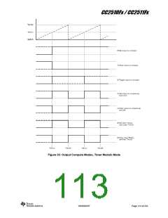
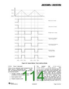
Figure 34: Output Modes, Timer Up/Down Mode
12.6.6 Timer 1 Interrupts
The
T1CTL.CH0IF,
register
bits
T1CTL.OVFIF,
and
T1CTL.CH1IF,
There is one interrupt vector assigned to the
T1CTL.CH2IF contains the interrupt flags for
the terminal count value event (overflow), and
the three channel compare/capture events,
respectively. These flags will be asserted
regardless off the channel n interrupt mask bit
(T1CCTLn.IM). The CPU interrupt flag,
IRCON.T1IF will only be asserted if one or
more of the channel n interrupt mask bits are
set to 1. An interrupt request is only generated
when the corresponding interrupt mask bit is
timer. This is T1 (Interrupt #9, see
39). The following timer events may generate
an interrupt request:
Table
• Counter reaches terminal count value
(overflow) or turns around on zero
• Input capture event
• Output compare event
SWRS055F
Page 114 of 241

 TI [ TEXAS INSTRUMENTS ]