bq25505
SLUSBJ3B –AUGUST 2013–REVISED JANUARY 2014
www.ti.com
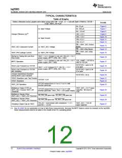
TYPICAL CHARACTERISTICS
Table of Graphs
Unless otherwise noted, graphs were taken using with CIN = 4.7µF, L1 = Coilcraft 22µH LPS4018, CSTOR =
4.7µF, VBAT_OV=4.2V
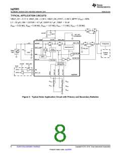
FIGURE
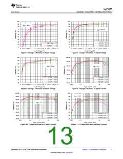
IN= 10 µA
Figure 6
Figure 7
Figure 8
Figure 9
Figure 10
Figure 11
Figure 12
vs. Input Voltage
vs. Input Current
IN= 100 µA
IIN = 10 mA
VIN = 2.0 V
VIN = 1.0 V
VIN = 0.5 V
VIN = 0.2 V
Charger Efficiency (η)(1)
EN = VBAT_SEC (Active
Mode)
Figure 13
Figure 14
Figure 15
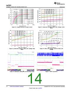
VBAT_SEC Quiescent Current
VBAT_PRI Leakage Current
vs. VBAT_SEC Voltage
vs. VBAT_PRI Voltage
EN = GND (Ship Mode)
EN = VBAT_SEC (Ship
Mode)
Startup by Taking EN Low (from
Ship mode)
VBAT = 3.4-V charged Li coin cell; VIN_DC = 1.0 V
power supply; MPPT=50%; ZIN = 100Ω
Figure 16
Figure 17
Figure 18
Figure 19
Figure 20
VBAT = 3.2-V charged Li coin cell; VIN_DC = 2.0 V VOC_SAMP = VSTOR to
power supply; ZIN = 100Ω
MPPT Operation
GND to VSTOR
R(VSTOR) = open to 84
Ω to open
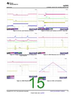
50mA Load Transient on VSTOR
VBAT = 4.2V charged 0.5 F; VIN_DC = 1.5 V
power supply; MPPT=80%; ZIN = 75Ω
50mA Load Transient on VSTOR
with Sampling
R(VSTOR) = open to 84
Ω to open
Charger Operational Waveform
During 50mA Load Transient
R(VSTOR) = 84 Ω
VRDIV Waveform over Two Periods
VRDIV Waveform
Figure 21
Figure 22
VSTOR = 4.2V
VSTOR ramped from 0 V to 4.2 V to 0 V with
function generator
VBAT_OK Operation
Figure 23
Multiplexor Output (VOR) as
VBAT_SEC Crosses VBAT_OK
Threshold
VBAT_SEC = 0.5 F super
capacitor; 1kΩ load on
VOR
VSTOR ramped from 0 V to 4.2 V to 0 V with
function generator; VBAT_PRI = 3.6V power supply
Figure 24
Multiplexor Signals When
VBAT_SEC > VBAT_OK Threshold
VB_PRI_ON goes high; VB_SEC_ON goes low
VB_PRI_ON goes low; VB_SEC_ON goes low
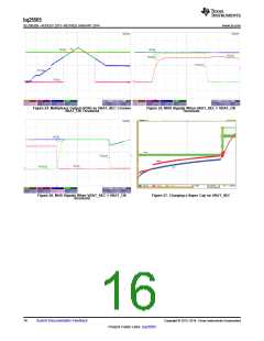
Figure 25
Figure 26
Figure 27
Multiplexor Signals When
VBAT_SEC < VBAT_OK Threshold
VIN_DC = sourcemeter with compliance = 1.2 V
and ISC = 1.0 mA
VBAT_SEC = 120 mF
super capacitor
Charging a Super Cap on VBAT
(1) See SLUA691 for an explanation on how to take these measurements. Because the MPPT feature cannot be disabled on the bq25505,
these measurements need to be taken in the middle of the 16 s sampling period.
12
Submit Documentation Feedback
Copyright © 2013–2014, Texas Instruments Incorporated
Product Folder Links :bq25505

 TI [ TEXAS INSTRUMENTS ]