bq20z80-V101
www.ti.com
SLUS625D–SEPTEMBER 2004–REVISED OCTOBER 2005
If the timer of either of the first two tiers expires during discharging, the discharge FET is turned off and the
ZVCHG FET is turned on if DF:Operation Cfg A [ZVCHG1, ZVCHG0] are set appropriately. When this occurs the
AFE_Current_Fault timer is started from 0, SBS.ChargingCurrent( ) is set to DF:Pre-Charge Current,
SBS.OperationStatus( ) [XDSG] is set, SBS.BatteryStatus( ) [TDA] is set, and the correct tier flag is set in
SBS.SafetyStatus( ).
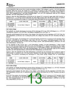
When the bq29312A detects a discharge-overcurrent fault, the charge and discharge FETs are turned off, the
XALERT pin of the bq20z80 is driven low by the XALERT pin of the bq29312, and the bq29312A is interrogated.
When the bq20z80 identifies the overcurrent condition, the AFE_Current_Fault timer is started from 0,
SBS.BatteryStatus( ) [TDA] is set, SBS.ChargingCurrent( ) is set to 0, and SBS.SafetyStatus( ) [AOCD] is set.
However, when the bq20z80 has any of SBS.SafetyStatus( ) [OCD, OCD2, AOCD] set, the FETs are turned on
again, as long as SBS.Current( ) is reported to be ≤ (-) DF:Dsg Current Threshold. No other flags change state
until full recovery is reached. This prevents overheating the charge-FET body diode during discharge. This action
is not affected by the state of DF:Operation Cfg B [NR].
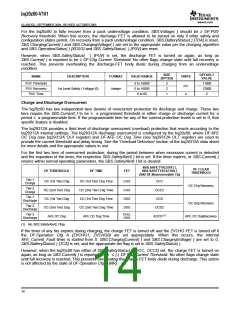
The bq20z80 can individually configure each overcurrent-protection feature to recover via two different methods
based on DF:Operation Cfg B [NR].
Standard Recovery, where DF:Operation Cfg B [NR] = 0, and the overcurrent tier is not selected in
DF:Non-Removable Cfg. When the pack is removed and reinserted the condition is cleared. Pack removal and
reinsertion is detected by a low-to-high-to-low transition on the PRES input. When the tier is not selected in
DF:Non-Removable Cfg, that particular feature uses the Non-Removable Battery Mode recovery.
Nonremovable Battery Mode Recovery where DF:Operation Cfg B [NR] = 1. The state of DF:Non-Removable
Cfg has no consequence when DF:Operation Cfg B [NR] = 1. This recovery requires SBS.AverageCurrent( ) to
be ≤ the respective recovery threshold, and for the AFE_Current_Fault timer ≥ DF:Current Recovery Time.
When a charging-fault recovery condition is detected, then the charge FET is allowed to be turned on, if other
safety and configuration states permit, the ZVCHG FET is turned off if DF:Operation Cfg A [ZVCHG1, ZVCHG0]
are set appropriately, SBS.BatteryStatus( ) [TCA] is reset, SBS.ChargingCurrent( ) and SBS.ChargingVoltage( )
are set to the appropriate value per the charging algorithm, and the appropriate SBS.SafetyStatus( ) flag is reset.
When a discharging-fault recovery condition is detected, the discharge FET is allowed to be turned on if other
safety and configuration states permit the ZVCHG FET is turned off if DF:Operation Cfg A [ZVCHG1, ZVCHG0]
are set appropriately, SBS.BatteryStatus( ) [TDA] is reset, SBS.ChargingCurrent( ) and SBS.ChargingVoltage( )
are set to the appropriate value per the charging algorithm and the SBS.OperationStatus( ) [XDSG] and the
appropriate SBS.SafetyStatus( ) flags are reset.
VALID
RANGE
SIZE
(BYTES)
DEFAULT
VALUE
NAME
CLASS / SUBCLASS
FORMAT
UNITS
OC (1st Tier) Chg
OC Chg Recovery
0 to 20000
0 to 1000
0 to 60
2
2
1
1
2
2
1
2
1
2
1
1
2
1
6000
200
2
mA
OC (1st Tier) Chg Time
Current Recovery Time
OC (1st Tier) Dsg
s
s
0 to 60
8
0 to 20000
0 to 1000
0 to 60
mA
mA
s
6000
200
5
OC Dsg Recovery
Integer
OC (1st Tier) Dsg Time
OC (2nd Tier) Chg
OC (2nd Tier) Chg Time
OC (2nd Tier) Dsg
1st Level Protection / Current (1)
0 to 20000
0 to 60
mA
s
8000
2
0 to 20000
0 to 60
mA
s
6000
2
OC (2nd Tier) Dsg Time
AFE OC Dsg
Hex
Integer
Hex
00 to 1f
N/A
mA
N/A
0x12
100
0x0f
AFE OC Dsg Recovery
AFE OC Dsg Time
10 to 1000
00 to 0f
15

 TI [ TEXAS INSTRUMENTS ]