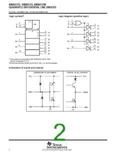
AM26C31C, AM26C31I, AM26C31M
QUADRUPLE DIFFERENTIAL LINE DRIVERS
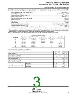
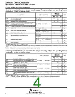
SLLS103G – DECEMBER 1990 – REVISED SEPTEMBER 1998
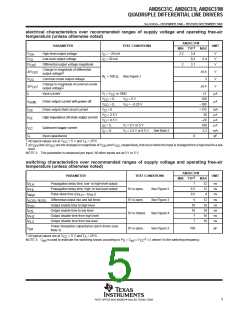
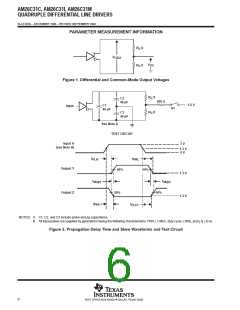
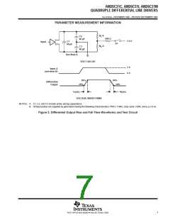
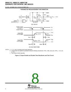
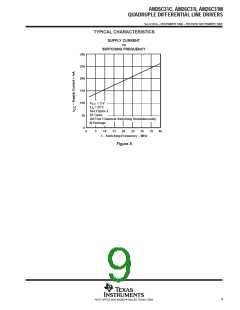
PARAMETER MEASUREMENT INFORMATION
R /2
L
C2
40 pF
500 Ω
1.5 V
C1
40 pF
Input
S1
R /2
L
C3
40 pF
See Note A
TEST CIRCUIT
3 V
0 V
Input A
(see Note B)
90%
10%
90%
10%
Differential
Output
t
t
f(OD)
r(OD)
VOLTAGE WAVEFORMS
NOTES: A. C1, C2, and C3 include probe and jig capacitance.
B. All input pulses are supplied by generators having the following characteristics: PRR ≤ 1 MHz, duty cycle ≤ 50%, and t , t ≤ 6 ns.
r f
Figure 3. Differential Output Rise and Fall Time Waveforms and Test Circuit
7
POST OFFICE BOX 655303 • DALLAS, TEXAS 75265

 TI [ TEXAS INSTRUMENTS ]