ADS7056
ZHCSG66 –MARCH 2017
www.ti.com.cn
10 Power Supply Recommendations
10.1 AVDD and DVDD Supply Recommendations
The device has two separate power supplies: AVDD and DVDD. AVDD powers the analog blocks and is also
used as the reference voltage for the analog-to-digital conversion. Always set the AVDD supply to be greater
than or equal to the maximum input signal to avoid saturation of codes. Decouple the AVDD pin to the GND pin
with a 3.3-µF ceramic decoupling capacitor.
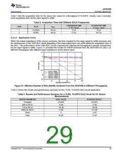
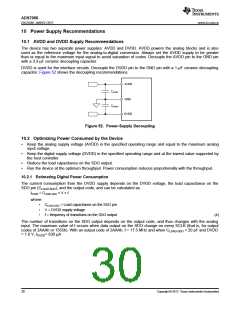
DVDD is used for the interface circuits. Decouple the DVDD pin to the GND pin with a 1-µF ceramic decoupling
capacitor. Figure 52 shows the decoupling recommendations.
AVDD
CAVDD
GND
CDVDD
DVDD
Figure 52. Power-Supply Decoupling
10.2 Optimizing Power Consumed by the Device
•
Keep the analog supply voltage (AVDD) in the specified operating range and equal to the maximum analog
input voltage.
•
Keep the digital supply voltage (DVDD) in the specified operating range and at the lowest value supported by
the host controller.
•
•
Reduce the load capacitance on the SDO output.
Run the device at the optimum throughput. Power consumption reduces proportionally with the throughput.
10.2.1 Estimating Digital Power Consumption
The current consumption from the DVDD supply depends on the DVDD voltage, the load capacitance on the
SDO pin (CLOAD-SDO), and the output code, and can be calculated as:
IDVDD = CLOAD-SDO × V × f
where:
•
•
•
CLOAD-SDO = Load capacitance on the SDO pin
V = DVDD supply voltage
f = frequency of transitions on the SDO output
(4)
The number of transitions on the SDO output depends on the output code, and thus changes with the analog
input. The maximum value of f occurs when data output on the SDO change on every SCLK (that is, for output
codes of 2AAAh or 1555h). With an output code of 2AAAh, f = 17.5 MHz and when CLOAD-SDO = 20 pF and DVDD
= 1.8 V, IDVDD= 630 µA.
30
Copyright © 2017, Texas Instruments Incorporated

 TI [ TEXAS INSTRUMENTS ]