ADS7056
ZHCSG66 –MARCH 2017
www.ti.com.cn
Typical Applications (continued)
9.2.1.2.1 Low Distortion Charge Kickback Filter Design
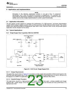
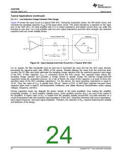
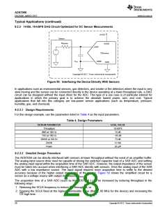
Figure 44 shows the input circuit of a typical SAR ADC. During the acquisition phase, the SW switch closes and
connects the sampling capacitor (CSH) to the input driver circuit. This action introduces a transient on the input
pins of the SAR ADC. An ideal amplifier with 0 Ω of output impedance and infinite current drive can settle this
transient in zero time. For a real amplifier with non-zero output impedance and finite drive strength, this switched
capacitor load can create stability issues.
Charge Kickback Filter
SAR ADC
-
RFLT
SW
CSH
+
VIN
CFLT
1
f-3dB
=
2 Πx RFLT x CFLT
Figure 44. Input Sample-and-Hold Circuit for a Typical SAR ADC
For ac signals, the filter bandwidth must be kept low to band-limit the noise fed into the ADC input, thereby
increasing the signal-to-noise ratio (SNR) of the system. Besides filtering the noise from the front-end drive
circuitry, the RC filter also helps attenuate the sampling charge injection from the switched-capacitor input stage
of the ADC. A filter capacitor, CFLT, is connected across the ADC inputs. This capacitor helps reduce the
sampling charge injection and provides a charge bucket to quickly charge the internal sample-and-hold
capacitors during the acquisition process. As a rule of thumb, the value of this capacitor is at least 20 times the
specified value of the ADC sampling capacitance. For this device, the input sampling capacitance is equal to
16 pF. Thus, the value of CFLT is greater than 320 pF. Select a COG- or NPO-type capacitor because these
capacitor types have a high-Q, low-temperature coefficient, and stable electrical characteristics under varying
voltages, frequency, and time.
Driving capacitive loads can degrade the phase margin of the input amplifiers, thus making the amplifier
marginally unstable. To avoid amplifier stability issues, series isolation resistors (RFLT) are used at the output of
the amplifiers. A higher value of RFLT is helpful from the amplifier stability perspective, but adds distortion as a
result of interactions with the nonlinear input impedance of the ADC. Distortion increases with source impedance,
input signal frequency, and input signal amplitude. Therefore, the selection of RFLT requires balancing the stability
and distortion of the design.
24
Copyright © 2017, Texas Instruments Incorporated

 TI [ TEXAS INSTRUMENTS ]