fosc
fosc
DEFINITION OF TERMS
An attempt has been made to be consistent with the termi-
nology used in this data sheet. In that regard, the definition
of each term is given as follows:
fMOD
=
=
128 • 2SPEED
mfactor
PGA SETTING
SAMPLING FREQUENCY
fOSC
1, 2, 4, 8
f SAMP
f SAMP
f SAMP
=
=
=
Analog Input Voltage—the voltage at any one analog input
relative to GND.
mfactor
fOSC • 2
16
32
mfactor
Analog Input Differential Voltage—given by the following
equation: (IN+) – (IN–). Thus, a positive digital output is
produced whenever the analog input differential voltage is
positive, while a negative digital output is produced whenever
the differential is negative.
fOSC • 4
mfactor
fOSC • 8
64, 128
f SAMP
=
mfactor
For example, when the converter is configured with a 2.5V
reference and placed in a gain setting of 1, the positive
full-scale output is produced when the analog input differen-
tial is 2.5V. The negative full-scale output is produced when
the differential is –2.5V. In each case, the actual input
voltages must remain within the GND to VDD range.
fSAMP—the frequency, or switching speed, of the input sam-
pling capacitor. The value is given by one of the following
equations:
f
DATA—the frequency of the digital output data produced by
the ADS1242 and ADS1243, fDATA is also referred to as the
Data Rate.
Conversion Cycle—the term conversion cycle usually refers
to a discrete A/D conversion operation, such as that per-
formed by a successive approximation converter. As used
here, a conversion cycle refers to the tDATA time period.
Full-Scale Range (FSR)—as with most A/D converters, the
full-scale range of the ADS1242 and ADS1243 is defined as
the input, that produces the positive full-scale digital output
minus the input, that produces the negative full-scale digital
output.
Data Rate—The rate at which conversions are completed.
See definition for fDATA
.
For example, when the converter is configured with a 2.5V
reference and is placed in a gain setting of 2, the full-scale
range is: [1.25V (positive full-scale) minus –1.25V (negative
full-scale)] = 2.5V.
fosc
fDATA
=
128 • 2SPEED • 1280 • 2DR
SPEED = 0,1
DR = 0,1, 2
Least Significant Bit (LSB) Weight—this is the theoretical
amount of voltage that the differential voltage at the analog
input has to change in order to observe a change in the
output data of one least significant bit. It is computed as
follows:
fOSC—the frequency of the crystal oscillator or CMOS com-
patible input signal at the XIN input of the ADS1242 and
ADS1243.
f
MOD—the frequency or speed at which the modulator of the
ADS1242 and ADS1243 is running. This depends on the
SPEED bit as given by the following equation:
Full − ScaleRange
LSB Weight =
2N – 1
SPEED = 0
SPEED = 1
where N is the number of bits in the digital output.
mfactor
128
256
tDATA—the inverse of fDATA, or the period between each data
output.
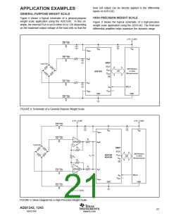
+5V SUPPLY ANALOG INPUT(1)
GENERAL EQUATIONS
DIFFERENTIAL
FULL-SCALE RANGE INPUT VOLTAGES(2)
PGA OFFSET
RANGE
FULL-SCALE
RANGE
DIFFERENTIAL
INPUT VOLTAGES(2)
PGA SHIFT
RANGE
GAIN SETTING
1
2
5V
±2.5V
±1.25V
±0.625V
2.5V
±1.25V
4
1.25V
±0.625V
±312.5mV
±156.25mV
±78.125mV
±39.0625mV
±19.531mV
±9.766mV
RANGE = 0
8
0.625V
±312.5mV
±156.25mV
±78.125mV
±39.0625mV
±19.531mV
16
32
64
128
312.5mV
156.25mV
78.125mV
39.0625mV
VREF
PGA
±V
±V
REF
REF
2 • PGA
4 • PGA
RANGE = 1
NOTES: (1) With a +2.5V reference. (2) Refer to electrical specification for analog input voltage range.
TABLE VI. Full-Scale Range versus PGA Setting.
ADS1242, 1243
22
SBAS235B
www.ti.com

 TI [ TEXAS INSTRUMENTS ]