ꢀ
ꢀ
ꢀ
ꢁꢂ
ꢁꢂ
ꢁꢇ
ꢃ
ꢃ
ꢃ
ꢄ
ꢄ
ꢄ
ꢄꢅ
ꢆꢅ
ꢆꢅ
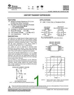
www.ti.com
SLLS266F − FEBRUARY 1997 − REVISED JULY 2004
This integrated circuit can be damaged by ESD. Texas Instruments recommends that all integrated circuits be handled with appropriate
precautions. Failure to observe proper handling and installation procedures can cause damage.
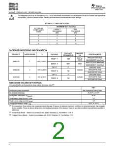
IEC1000-4-2 COMPLIANCE LEVEL
MAXIMUM TEST VOLTAGE
IEC1000-4-2
CONTACT
DISCHARGE
(kV)
AIR
DISCHARGE
(kV)
COMPLIANCE
LEVEL
1
2
3
4
2
4
6
8
2
4
8
15
PACKAGE/ORDERING INFORMATION
PACKAGE
DESIGNATOR
MARKED
AS
PRODUCT
SUPRESSORS
T
A
PACKAGE
ORDER NUMBER
SN65220YZBR (Reel)
SN65220YZBT (Mini Reel)
SN65220DBVR (Mini Reel)
SN65220DBVT (Mini Reel)
SN65240P (Rail)
NWP or
65220
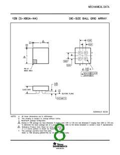
WCSP−4
YZB
SN65220
1
−40°C to 85°C
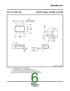
SOT23−6
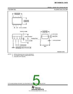
DIP−8
DBV
P
SADI
SN65240PW (Rail)
SN65240
SN75240
2
2
−40°C to 85°C
0°C to 70°C
A65240
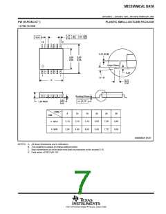
TSSOP−8
DIP−8
PW
P
SN65240PWR (Reel)
SN75240P (Rail)
SN75240PW (Rail)
A75240
TSSOP−8
PW
SN75240PWR (Reel)
ABSOLUTE MAXIMUM RATINGS
over operating free-air temperature range unless otherwise noted
(1)
UNIT
Continuous power dissipation
Electrostatic discharge
See Dissipation Rating Table
(2)
(3)
15 kV , 2 kV
Peak power dissipation, P
D(peak)
60 W
3 A
Peak forward surge current, I
Peak reverse surge current, I
FSM
RSM
−9 A
Storage temperature range, T
stg
−65°C to 150°C
(1)
Stresses above these ratings may cause permanent damage. Exposure to absolute maximum conditions for extended periods may degrade
device reliability. These are stress ratings only, and functional operation of the device at these or any other conditions beyond those specified is
not implied.
(2)
(3)
Human Body Model − Tested in accordance with JEDEC Standard 22, Test Method A114−A.
Charged Device Model − Tested in accordance with JEDEC Standard 22, Test Method C101.
2

 TI [ TEXAS INSTRUMENTS ]