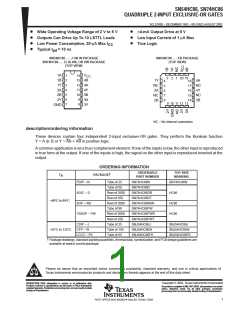
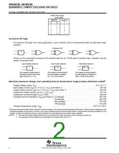
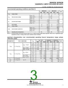
SN54HC86, SN74HC86
QUADRUPLE 2-INPUT EXCLUSIVE-OR GATES
SCLS100E – DECEMBER 1982 – REVISED AUGUST 2003
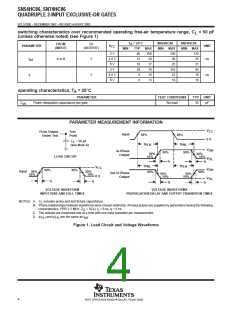
switching characteristics over recommended operating free-air temperature range, C = 50 pF
L
(unless otherwise noted) (see Figure 1)
T
A
= 25°C
TYP
40
SN54HC86
MIN MAX
SN74HC86
MIN MAX
FROM
(INPUT)
TO
(OUTPUT)
PARAMETER
V
UNIT
CC
MIN
MAX
100
20
2 V
4.5 V
6 V
150
30
125
25
21
95
19
16
t
A or B
Y
Y
12
ns
pd
t
10
17
25
2 V
28
75
110
22
t
4.5 V
6 V
8
15
ns
6
13
19
operating characteristics, T = 25°C
A
PARAMETER
TEST CONDITIONS
TYP
UNIT
C
Power dissipation capacitance per gate
No load
35
pF
pd
PARAMETER MEASUREMENT INFORMATION
V
CC
From Output
Under Test
Test
Point
Input
50%
50%
0 V
C
= 50 pF
L
t
t
PLH
PHL
90%
(see Note A)
V
V
OH
In-Phase
Output
90%
t
50%
10%
50%
10%
LOAD CIRCUIT
OL
t
r
f
f
t
t
PLH
PHL
90%
V
CC
V
V
90%
t
90%
OH
Input
50%
10%
50%
10%
90%
t
Out-of-Phase
Output
50%
10%
50%
10%
0 V
OL
t
r
f
t
r
VOLTAGE WAVEFORM
INPUT RISE AND FALL TIMES
VOLTAGE WAVEFORMS
PROPAGATION DELAY AND OUTPUT TRANSITION TIMES
NOTES: A.
B. Phase relationships between waveforms were chosen arbitrarily. All input pulses are supplied by generators having the following
characteristics: PRR ≤ 1 MHz, Z = 50 Ω, t = 6 ns, t = 6 ns.
C includes probe and test-fixture capacitance.
L
O
r
f
C. The outputs are measured one at a time with one input transition per measurement.
D. and t are the same as t
t
.
pd
PLH
PHL
Figure 1. Load Circuit and Voltage Waveforms
4
POST OFFICE BOX 655303 • DALLAS, TEXAS 75265

 TI [ TEXAS INSTRUMENTS ]