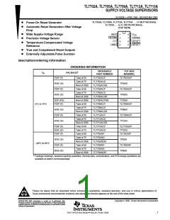
TL7702A, TL7705A, TL7709A, TL7712A, TL7715A
SUPPLY-VOLTAGE SUPERVISORS
SLVS028H – APRIL 1983 – REVISED MAY 2003
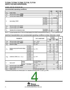
recommended operating conditions
MIN
3.5
2
MAX
UNIT
V
V
CC
V
IH
V
IL
Supply voltage
18
High-level input voltage at RESIN
Low-level input voltage at RESIN
V
0.6
V
TL7702A
TL7705A
TL7709A
TL7712A
TL7715A
0
0
0
0
0
See Note 2
10
15
V
I
Input voltage, SENSE
V
20
20
I
I
High-level output current, RESET
Low-level output current, RESET
–16
16
mA
mA
OH
OL
TL77xxAC
TL77xxAI
0
70
85
T
A
Operating free-air temperature range
°C
–40
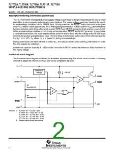
NOTE 2: For proper operation of the TL7702A, the voltage applied to the SENSE terminal should not exceed V
CC
– 1 V or 6 V, whichever is less.
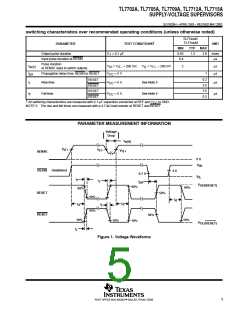
electrical characteristics over recommended operating conditions (unless otherwise noted)
TL77xxAC
TL77xxAI
†
PARAMETER
UNIT
TEST CONDITIONS
MIN
TYP
MAX
V
V
High-level output voltage, RESET
Low-level output voltage, RESET
Reference voltage
I
I
= –16 mA
V –1.5
CC
V
V
V
OH
OH
= 16 mA
0.4
2.58
2.58
4.6
OL
OL
V
ref
T
= 25°C
2.48
2.48
4.5
2.53
2.53
4.55
7.6
10.8
13.5
10
A
TL7702A
TL7705A
TL7709A
TL7712A
TL7715A
TL7702A
TL7705A
TL7709A
TL7712A
TL7715A
Negative-going input threshold voltage,
SENSE
V
IT–
T
= 25°C
7.5
7.7
V
A
10.6
13.2
11
13.8
15
V
hys
Hysteresis, SENSE (V
Input current
– V
)
T = 25°C
A
20
mV
IT+
IT–
35
45
V = 2.4 V to V
I
20
–100
2
CC
– 1.5 V
CC
RESIN
I
I
V = 0.4 V
I
µA
SENSE
TL7702A
V
< V < V
I
0.5
1.8
ref
I
I
I
High-level output current, RESET
Low-level output current, RESET
Supply current
V
= 18 V
= 0
50
µA
µA
OH
O
O
V
–50
3
OL
CC
All inputs and outputs open
mA
†
All electrical characteristics are measured with 0.1-µF capacitors connected at REF, CT, and V
to GND.
CC
4
POST OFFICE BOX 655303 • DALLAS, TEXAS 75265

 TI [ TEXAS INSTRUMENTS ]