71M6521DE/71M6521FE
Energy Meter IC
DATASHEET
JANUARY 2008
Optical Interface
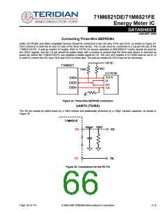
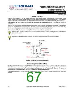
The pins OPT_TX and OPT_RX can be used for a regular serial interface, e.g. by connecting a RS_232 transceiver, or they
can be used to directly operate optical components, e.g. an infrared diode and phototransistor implementing a FLAG interface.
Figure 36 shows the basic connections. The OPT_TX pin becomes active when the I/O RAM register OPT_TXDIS is set to 0.
The polarity of the OPT_TX and OPT_RX pins can be inverted with configuration bits OPT_TXINV and OPT_RXINV, re-
spectively.
The OPT_TX output may be modulated at 38kHz when system power is present. Modulation is not available in BROWNOUT
mode. The OPT_TXMOD bit enables modulation. The duty cycle is controlled by OPT_FDC[1:0], which can select 50%, 25%,
12.5%, and 6.25% duty cycle. A 6.25% duty cycle means OPT_TX is low for 6.25% of the period.
The receive pin (OPT_RX) may need an analog filter when receiving modulated optical signals.
With modulation, an optical emitter can be operated at higher current than nominal, enabling it to increase the distance
along the optical path.
If operation in BROWNOUT mode is desired, the external components should be connected to V3P3D.
V3P3SYS
R1
71M6521
100kΩ
100pF
OPT_RX
Phototransistor
V3P3SYS
LED
R2
OPT_TX
Figure 36: Connection for Optical Components
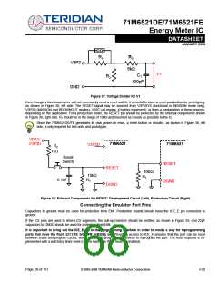
Connecting V1 and Reset Pins
A voltage divider should be used to establish that V1 is in a safe range when the meter is in mission mode (V1 must be lower
than 2.9V in all cases in order to keep the hardware watchdog timer enabled). For proper debugging or loading code into the
71M6521DE/FE mounted on a PCB, it is necessary to have a provision like the header shown above R1 in Figure 37. A
shorting jumper on this header pulls V1 up to V3P3 disabling the hardware watchdog timer.
The parallel impedance of R1 and R2 should be approximately 20 to 30kΩ in order to provide hysteresis for the power fault
monitor.
v1.0
© 2005-2008 TERIDIAN Semiconductor Corporation
Page: 67 of 101

 TERIDIAN [ TERIDIAN SEMICONDUCTOR CORPORATION ]