71M6521DE/71M6521FE
Energy Meter IC
DATASHEET
JANUARY 2008
APPLICATION INFORMATION
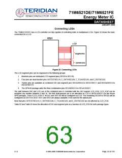
Connection of Sensors (CT, Resistive Shunt)
Figure 28 and Figure 29 show how resistive dividers, current transformers, and restive shunts are connected to the voltage and
current inputs of the 71M6521DE/FE.
Vout = R * Iout = R * Iin/N
core
Iin
VA = Vin * Rout/(Rout + Rin)
Iout
Iin
VA
IA
R
Vout
Rin
Vin
Rout
V3P3
1/N
Filter
Iout
Figure 28: Resistive Voltage Divider (Left), Current Transformer (Right)
Vout = R * Iin
Iin
IA
R
Vout
V3P3
Iin
Figure 29: Resistive Shunt
v1.0
© 2005-2008 TERIDIAN Semiconductor Corporation
Page: 59 of 101

 TERIDIAN [ TERIDIAN SEMICONDUCTOR CORPORATION ]