71M6521DE/71M6521FE
Energy Meter IC
DATASHEET
JANUARY 2008
RESET
MISSION
V3P3SYS
falls
V1 > VBIAS
V1 <= VBIAS
IE_PLLRISE
-> 1
IE_PLLFALL
-> 1
V3P3SYS
rises
V3P3SYS
rises
LCD_ONLY
BROWNOUT
V3P3SYS
rises
RESET &
VBAT_OK
IE_PB -> 1
IE_WAKE ->
1
PB
SLEEP or
VBAT_OK
timer
LCD
timer
PB
VBAT_OK
VBAT_OK
RESET &
VBAT_OK
SLEEP
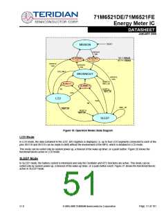
Figure 18: Operation Modes State Diagram
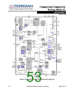
LCD Mode
In LCD mode, the data contained in the LCD_SEG registers is displayed, i.e. up to four LCD segments connected to each of the
pins SEG18 and SEG19 can be made to blink without the involvement of the MPU, which is disabled in LCD mode.
This mode can be exited only by system power up, a timeout of the wake-up timer, or a push button. Figure 20 shows the
functional blocks active in LCD mode.
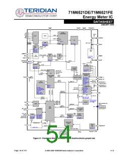
SLEEP Mode
In SLEEP mode, the battery current is minimized and only the Oscillator and RTC functions are active. This mode can be
exited only by system power-up, a timeout of the wake-up timer, or a push button event. Figure 21 shows the functional blocks
active in SLEEP mode.
v1.0
© 2005-2008 TERIDIAN Semiconductor Corporation
Page: 51 of 101

 TERIDIAN [ TERIDIAN SEMICONDUCTOR CORPORATION ]