Package Dimensions
Data Sheets
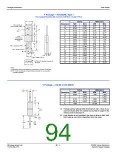
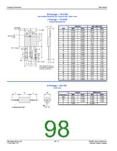
F Package — TO-202AB, Type 1
Non-isolated Mounting Tab Common with MT2 / Anode / PIN 2
A
B
Inches
Millimeters
Dimension
MIN
MAX
0.385
0.253
0.120
0.810
0.310
0.430
0.062
0.065
0.029
0.105
0.205
0.059
0.023
0.065
0.185
0.130
0.405
MIN
9.27
6.17
2.79
19.81
7.37
10.16
1.32
1.40
0.58
2.41
4.95
1.24
0.43
1.40
4.45
3.15
9.91
MAX
9.78
6.43
3.05
20.57
7.87
10.92
1.58
1.65
0.74
2.67
5.21
1.50
0.58
1.65
4.70
3.30
10.29
Tab Common to
MT2 / Anode / PIN 2
A
B
C
D
E
F
G
H
J
0.365
0.243
0.110
0.780
0.290
0.400
0.052
0.055
0.023
0.095
0.195
0.049
0.017
0.055
0.175
0.124
0.390
C
E
R
DIA.
G
D
F
Case
Temperature
Measurement
Point
MT1 / Cathode / PIN 1
K
L
H
J
MT2 / Anode / PIN 2
M
M
N
P
Q
R
S
N
P
K
Q
L
Gate / Trigger / PIN 3
0.070 x 45 Chamfer Common to
All Types
˚
S
Notes:
(1) Maximum torque to be applied to mounting tab is 8 in-lbs. (0.904 Nm)
(2) Pin 2 and mounting tab are electrically connected. Do not use either
for Sidac operation.
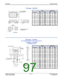
Y Package — DO-35 or DO-204AH
A
DIA.
Inches
Millimeters
1
Dimension
MIN
MAX
0.090
0.015
0.165
0.022
MIN
MAX
2.280
0.381
4.190
0.558
A
B
C
D
E
0.060
1.530
B
0.135
0.018
1.000
3.430
0.458
25.400
C
(1) Package contour optional within dimensions A and C. Slugs, if any,
shall be included within this cylinder but shall not be subject to the
minimum limit of Dimension A.
1
(2) Lead diameter is not controlled in this zone to allow for flash, lead
finish build-up, and minor irregularities other than slugs.
B
2
E
TYP
D
DIA.
TYP
http://www.teccor.com
+1 972-580-7777
M1 - 2
2002 Teccor Electronics
Thyristor Product Catalog

 TECCOR [ TECCOR ELECTRONICS ]