Rectifiers
Data Sheets
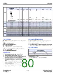
Part Number
I2t
VRRM
VR
IF(AV)
(1)
IF(RMS)
IFSM
(2)
IRM
(3)
VFM
RθJC
Isolated
Type
Not
Used
C
A
Amps
mA
Volts
TC
=
TC
=
TC =
TO-220
Volts
Volts
Amps
Amps
Amps2Sec
°C/W
60/50 Hz
25 °C
100 °C
125 °C
TC=25 °C
See “Package Dimensions”
section for variations. (4)
MIN
200
400
600
800
1000
200
400
600
800
1000
200
400
600
800
1000
MIN
200
400
600
800
1000
200
400
600
800
1000
200
400
600
800
1000
MAX
9.5
9.5
9.5
9.5
MAX
15
15
15
15
15
20
20
20
20
20
25
25
25
25
25
MAX
0.5
0.5
0.5
0.5
3
0.5
0.5
0.5
0.5
3
0.5
0.5
0.5
0.5
3
MAX
1.6
1.6
1.6
1.6
1.6
1.6
1.6
1.6
1.6
1.6
1.6
1.6
1.6
1.6
1.6
TYP
2.85
2.85
2.58
2.85
2.85
2.5
2.5
2.5
2.5
2.5
D2015L
D4015L
D6015L
D8015L
DK015L
D2020L
D4020L
D6020L
D8020L
DK020L
D2025L
D4025L
D6025L
D8025L
DK025L
225/188
225/188
225/188
225/188
225/188
300/255
300/255
300/255
300/255
300/255
350/300
350/300
350/300
350/300
350/300
0.1
0.1
0.1
0.1
0.1
0.1
0.1
0.1
0.1
0.1
0.1
0.1
0.1
0.1
0.1
1
1
1
1
210
210
210
210
210
374
374
374
374
374
508
508
508
508
508
15 A
20 A
25 A
9.5
12.7
12.7
12.7
12.7
12.7
15.9
15.9
15.9
15.9
15.9
1
1
1
1
1
1
1
1
2.7
2.7
2.7
2.7
2.7
Test Conditions
Electrical Specification Notes
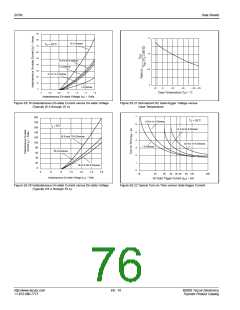
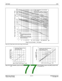
(1) See Figure E7.3 for current rating at specified case temperature.
(2) For more than one full cycle rating, see Figure E7.4.
(3) TC = TJ for test conditions
I2t — RMS surge (non-repetitive) forward current for 8.3 ms for fusing
IF(AV) — Average forward current
IF(RMS) — RMS forward current
IFSM — Peak one-cycle surge current
IRM — Peak reverse current
(4) See package outlines for lead form configurations. When ordering
special lead forming, add type number as suffix to part number.
R
JC — Thermal resistance (steady state) junction to case
θ
Electrical Isolation
V
V
V
FM — Peak forward voltage at rated average forward current
R — DC blocking voltage
RRM — Peak repetitive reverse voltage
Electrical Isolation
from Leads to Mounting Tab *
TO-220
General Notes
V AC RMS
2500
Isolated
Standard
Optional **
•
•
•
Operating temperature range (TJ) is -40 °C to +125 °C.
Storage temperature range (TS) is -40 °C to +125 °C.
Lead solder temperature is a maximum of 230 °C for 10 seconds
maximum at a minimum of 1/16" (1.59 mm) from case.
4000
* UL Recognized File #E71639
** For 4000 V isolation, use “V” suffix in the part number.
•
•
•
The case temperature (TC) is measured as shown on dimensional
outline drawings in the “Package Dimensions” section of this
catalog.
Teccor's electrically-isolated TO-220 devices withstand a high
potential test of 2500 V ac rms from leads to mounting tab over the
operating temperature range.
Typical Reverse Recovery Time (trr) is 4 µs. (Test conditions =
0.9 A forward current and 1.5 A reverse current)
http://www.teccor.com
+ 1 972-580-7777
E7 - 2
©2002 Teccor Electronics
Thyristor Product Catalog

 TECCOR [ TECCOR ELECTRONICS ]