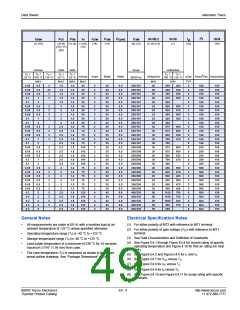
Data Sheets
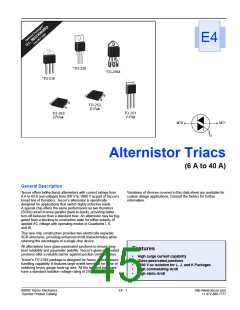
Alternistor Triacs
2
I
V
V
I
I
P
P
G(AV)
I
TSM
(9) (13)
tgt
(10)
dv/dt(c)
(1) (4) (13)
dv/dt
(1)
I t
di/dt
(19)
DRM
(1) (18)
GT
TM
H
GTM
(14)
GM
(14)
(2) (6) (1) (5) (1) (8)
(15) (17)
(20)
(12)
mAmps
Volts
Volts
TC
Amps
Volts/µSec
TC
=
TC
=
TC
=
TC
=
=
TC
=
TC =
mAmps Amps
MAX
Watts
Watts
Volts/µSec
µSec Amps2Sec Amps/µSec
TYP
25 °C 100 °C 125 °C
MAX
25 °C
MAX
1.5
1.5
1.5
1.5
1.5
2
25 °C
MAX
1.6
1.6
1.6
1.6
1.6
1.6
1.6
1.6
1.6
1.6
1.6
1.6
1.6
1.6
1.6
1.8
1.8
1.8
1.8
1.8
1.4
1.4
1.4
1.5
1.5
1.5
1.8
1.8
1.8
1.8
1.8
60/50 Hz
100 °C 125 °C
MIN
MIN
20
20
20
20
20
25
25
25
25
25
30
30
30
30
30
30
30
30
30
30
20
20
20
20
20
20
50
50
50
50
50
0.05
0.05
0.05
0.1
0.5
0.5
0.5
1
2
27
2
35
2
2
2
2
2
2
2
2
2
2
2
2
2
2
2
2
2
2
2
2
2
2
2
2
2
2
4
4
4
4
4
20
20
20
20
20
20
20
20
20
20
20
20
20
20
20
20
20
20
20
20
20
20
20
20
20
20
40
40
40
40
40
0.5
0.5
0.5
0.5
0.5
0.5
0.5
0.5
0.5
0.5
0.5
0.5
0.5
0.5
0.5
0.5
0.5
0.5
0.5
0.5
0.5
0.5
0.5
0.5
0.5
0.5
0.8
0.8
0.8
0.8
0.8
200/167
200/167
200/167
200/167
200/167
200/167
200/167
200/167
200/167
200/167
200/167
200/167
200/167
200/167
200/167
250/208
250/208
250/208
250/208
250/208
350/290
350/290
350/290
350/290
350/290
350/290
400/335
400/335
400/335
400/335
400/335
500
400
300
275
200
650
600
500
425
300
875
875
800
700
350
875
875
800
700
400
650
600
500
650
600
500
1100
1100
1000
900
500
400
350
250
200
3
3
3
3
3
3
3
3
3
3
5
5
5
5
5
5
5
5
5
5
3
3
3
3
3
3
5
5
5
5
5
166
166
166
166
166
166
166
166
166
166
166
166
166
166
166
259
259
259
259
259
508
508
508
508
508
508
664
664
664
664
664
100
100
100
100
100
100
100
100
100
100
100
100
100
100
100
100
100
100
100
100
100
100
100
100
100
100
150
150
150
150
150
35
35
35
35
3
0.1
3
0.05
0.05
0.05
0.1
0.5
0.5
0.5
1
2
2
2
3
50
50
50
50
500
475
400
350
2
2
2
2
0.1
3
50
70
70
70
70
70
0.05
0.05
0.05
0.1
0.5
0.5
0.5
1
2
2
2
3
2.5
2.5
2.5
2.5
2.5
2.5
2.5
2.5
2.5
2.5
2
600
600
520
475
0.1
3
0.05
0.05
0.05
0.1
0.5
0.5
0.5
1
2
2
2
3
100
100
100
100
100
75
600
600
520
475
0.1
3
0.05
0.05
0.05
0.05
0.05
0.05
0.2
0.2
0.2
0.2
0.2
0.5
0.5
0.5
0.5
0.5
0.5
2
2
2
2
5
2
2
2
2
2
2
5
5
5
5
500
475
400
500
475
400
700
700
625
575
2
2
2
2
75
75
75
75
2
75
2.5
2.5
2.5
2.5
2.5
120
120
120
120
120
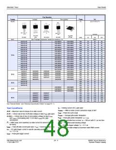
General Notes
Electrical Specification Notes
•
All measurements are made at 60 Hz with a resistive load at an
(1) For either polarity of MT2 with reference to MT1 terminal
ambient temperature of +25 °C unless specified otherwise.
(2) For either polarity of gate voltage (VGT) with reference to MT1
terminal
•
•
•
Operating temperature range (TJ) is -40 °C to +125 °C.
Storage temperature range (TS) is -40 °C to +125 °C.
Lead solder temperature is a maximum of 230 °C for 10 seconds
maximum ≥1/16" (1.59 mm) from case.
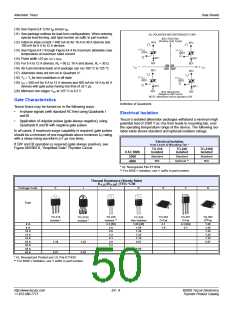
(3) See Gate Characteristics and Definition of Quadrants.
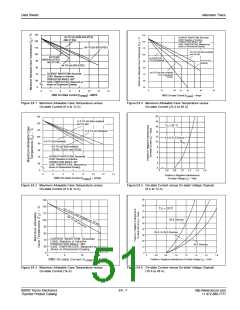
(4) See Figure E4.1 through Figure E4.4 for current rating at specific
operating temperature and Figure 4.16 for free air rating (no heat
sink).
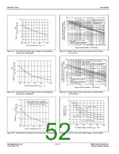
(5) See Figure E4.5 and Figure E4.6 for iT and vT.
(6) See Figure E4.7 for VGT versus TC.
(7) See Figure E4.8 for IGT versus TC.
•
The case temperature (TC) is measured as shown in the dimen-
sional outline drawings. See “Package Dimensions” section.
(8) See Figure E4.9 for IH versus TC.
(9) See Figure E4.10 and Figure E4.11 for surge rating with specific
durations.
©2002 Teccor Electronics
Thyristor Product Catalog
E4 - 5
http://www.teccor.com
+1 972-580-7777

 TECCOR [ TECCOR ELECTRONICS ]