AN1006
Application Notes
Model 577 Curve Tracer Procedure Notes
Because the curve tracer procedures in this application note are written for the Tektronix model 576 curve tracer, certain settings must
be adjusted when using model 577. Model 576 curve tracer has separate controls for polarity (AC,+,-) and mode (Norm, DC, Leakage),
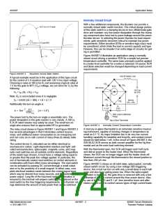
whereas Model 577 has only a polarity control. The following table shows the guidelines for setting Collector Supply Polarity when
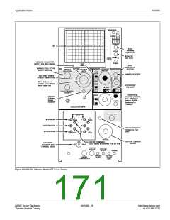
using model 577. (Figure AN1006.28)
Model 576
Model 577
If using Leakage mode along with polarity setting of +(NPN) and -(PNP),
set Collector Supply Polarity to either +DC or -DC, depending on polarity setting
specified in the procedure. The vertical scale is read directly from the scale on the
control knob.
[vertical scale divided by 1,000],
If using DC mode along with either +(NPN) or -(PNP) polarity,
set Collector Supply Polarity to either +DC or -DC depending on polarity
specified.
If using Norm mode along with either +(NPN) or -(PNP) polarity,
If using Norm mode with AC polarity,
set Collector Supply Polarity to either +(NPN) or -(PNP) per specified procedure.
set Collector Supply Polarity to AC.
One difference between models 576 and 577 is the Step/Offset
Polarity setting. The polarity is inverted when the button is
depressed on the Model 576 curve tracer. The Model 577 is
opposite the Step/Offset Polarity is “inverted” when the button
is extended and “Normal” when the button is depressed. The
Step/Offset Polarity is used only when measuring IGT and VGT of
triacs and Quadracs in Quadrants l through lV.
Also, the Variable Collector Supply Voltage Range and Power
Dissipation controls have different scales than model 576. The
following table shows the guidelines for setting Power Dissipation
when using model 577.
Model 576
If power dissipation is 0.1 W,
If power dissipation is 0.5 W,
If power dissipation is 2.2 W,
If power dissipation is 10 W,
If power dissipation is 50 W,
If power dissipation is 220 W,
Model 577
set at 0.15 W.
set at 0.6 W.
set at 2.3 W.
set at 9 W.
set at 30 W.
set at 100 W.
Although the maximum power setting on model 576 curve tracer
is 220 W (compared to 100 W for model 577), the maximum col-
lector current available is approximately the same. This is due to
the minimum voltage range on model 577 curve tracer being
6.5 V compared to 15 V for model 576. The following table shows
the guidelines for adapting Collector Voltage Supply Range set-
tings for model 577 curve tracer procedures:
Model 576
If voltage range is 15 V,
Model 577
set at either 6.5 V or 25 V, depending on parameter
being tested. Set at 6.5 V when measuring VTM (to
allow maximum collector current) and set at 25 V
when measuring IGT and VGT
.
If voltage range is 75 V,
set at 100 V.
If voltage range is 1500 V, set at 1600 V.
http://www.teccor.com
+1 972-580-7777
AN1006 - 18
©2002 Teccor Electronics
Thyristor Product Catalog

 TECCOR [ TECCOR ELECTRONICS ]