Application Notes
AN1006
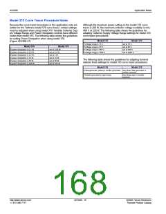
To continue testing, perform the following procedures.
3. Set Vertical knob to 50 µA/DIV.
4. Set Polarity to AC.
5. Set Mode to Norm.
6. Set Power Dissipation to 0.5 W. (0.4 W on 370)
7. Set Terminal Selector to Emitter Grounded-Open Base.
Procedure 9: VTM(Forward)
To measure the VTM (Forward) parameter:
1. Set Left-Right Terminal Jack Selector to correspond with
the location of the test fixture.
2. Increase Variable Collector Supply Voltage until current
reaches rated IT(peak), which is 1.4 times the IT(RMS) rating of
the sidac.
Note: Model 370 current is limited. Set to 400 mA. Check for
1.1 V MAX.
Procedure 2: VBO
To measure the VBO parameter:
1. Set Left-Right Terminal Jack Selector to correspond with
the location of the test fixture.
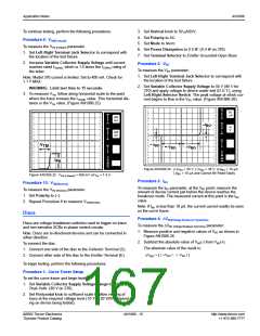
2. Set Variable Collector Supply Voltage to 55 V (65 V for
370) and apply voltage to device under test (D.U.T.), using
Left-Right-Selector Switch. The peak voltage at which cur-
rent begins to flow is the VBO value. (Figure AN1006.26)
WARNING: Limit test time to 15 seconds.
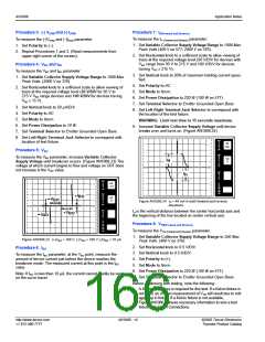
3. To measure VTM, follow along horizontal scale to the point
where the trace crosses the IT(peak) value. This horizontal dis-
tance is the VTM value. (Figure AN1006.25)
PER
V
50
E
PER
V
R
A
T
500
mA
E
DIV
R
T
PER
H
DIV
+I
BO
O
R
I
10
V
PER
H
O
Z
DIV
500
mV
R
I
Z
DIV
PER
S
T
I
E
P
PER
V
BO
TM
S
V
+V
BO
BO
T
E
P
()k
DIV
9m
PER
DIV
()k
DIV
9m
PER
DIV
I
PK
Figure AN1006.26 (+)VBO = 35 V; (-)VBO = 36 V; (±)IBO < 15 µA;
(-)IBO < 10 µA and Cannot Be Read Easily
Figure AN1006.25 VTM (Forward) = 950 mV at IPK = 1.4 A
Procedure 3: IBO
Procedure 10: VTM(Reverse)
To measure the IBO parameter, at the VBO point, measure the
amount of device current just before the device reaches the
breakover mode. The measured current at this point is the IBO
value.
To measure the VTM (Reverse) parameter:
1. Set Polarity to (–).
2. Repeat Procedure 8 to measure VTM(Reverse)
.
Note: If IBO is less than 10 µA, the current cannot readily be seen
on the curve tracer.
Diacs
Procedure 4: ∆VBO(Voltage Breakover Symmetry)
To measure the ∆VBO (Voltage Breakover Symmetry) parameter:
1. Measure positive and negative values of VBO as shown in
Figure AN1006.26.
2. Subtract the absolute value of VBO(-) from VBO(+).
The absolute value of the result is:
Diacs are voltage breakdown switches used to trigger-on triacs
and non-sensitive SCRs in phase control circuits.
Note: Diacs are bi-directional devices and can be connected in
either direction.
To connect the diac:
1. Connect one side of the diac to the Collector Terminal (C).
2. Connect other side of the diac to the Emitter Terminal (E).
∆V
= [ I +VBO I - I -VBO I ]
BO
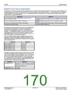
To begin testing, perform the following procedures.
Procedure 1: Curve Tracer Setup
To set the curve tracer and begin testing:
1. Set Variable Collector Supply Voltage Range to 75 Max
Peak Volts. (80 V on 370)
2. Set Horizontal knob to sufficient scale to allow viewing of
trace at the required voltage level (10 V to 20 V/DIV depend-
ing on device being tested).
©2002 Teccor Electronics
Thyristor Product Catalog
AN1006 - 15
http://www.teccor.com
+1 972-580-7777

 TECCOR [ TECCOR ELECTRONICS ]