AN1006
Application Notes
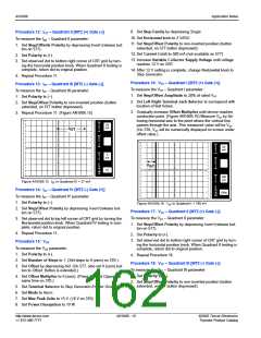
Procedure 3: (-) VDRM and (-) IDRM
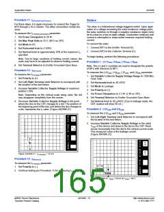
Procedure 7: IH(Forward and Reverse)
To measure the IH (Forward and Reverse) parameter:
To measure the (-)VDRM and (-)IDRM parameter:
1. Set Variable Collector Supply Voltage Range to 1500 Max
Peak Volts (400 V on 577; 2000 V on 370).
1. Set Polarity to (–).
2. Repeat Procedures 1 and 2. (Read measurements from
2. Set Horizontal knob to a sufficient scale to allow viewing of
trace at the required voltage level (50 V/DIV for devices with
upper right corner of the screen).
Procedure 4: VBO and IBO
To measure the VBO and IBO parameter:
1. Set Variable Collector Supply Voltage Range to 1500 Max
Peak Volts. (2000 V on 370)
VBO range from 95 V to 215 V and 100 V/DIV for devices
having VBO ≥ 215 V).
3. Set Vertical knob to 20% of maximum holding current speci-
fied.
4. Set Polarity to AC.
5. Set Mode to Norm.
6. Set Power Dissipation to 220 W (100 W on 577).
7. Set Terminal Selector to Emitter Grounded-Open Base.
2. Set Horizontal knob to a sufficient scale to allow viewing of
trace at the required voltage level (50 V/DIV for 95 V to
215 V VBO range devices and 100 V/DIV for devices having
V
BO ≥ 15 V).
3. Set Vertical knob to 50 µA/DIV.
4. Set Polarity to AC.
8. Set Left-Right Terminal Jack Selector to correspond with
the location of the test fixture.
5. Set Mode to Norm.
6. Set Power Dissipation to 10 W.
7. Set Terminal Selector to Emitter Grounded-Open Base.
WARNING: Limit test time to 15 seconds maximum.
9. Increase Variable Collector Supply Voltage until device
breaks over and turns on. (Figure AN1006.24)
8. Set Left-Right Terminal Jack Selector to correspond with
PER
V
location of test fixture.
20
mA
E
R
T
DIV
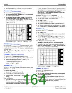
Procedure 5: VBO
PER
H
To measure the VBO parameter, increase Variable Collector
Supply Voltage until breakover occurs. (Figure AN1006.23) The
voltage at which current begins to flow and voltage on CRT does
not increase is the VBO value.
O
50
V
R
I
H
I
Z
DIV
PER
S
I
H
T
E
P
PER
V
50
E
R
A
T
()k
DIV
9m
DIV
PER
DIV
PER
H
+I
BO
O
R
I
50
V
V
BO
Figure AN1006.24 IH = 48 mA in both forward and reverse
directions
Z
DIV
PER
S
IH is the vertical distance between the center horizontal axis and
the beginning of the line located on center vertical axis.
+V
BO
T
I
E
P
BO
()k
DIV
9m
PER
DIV
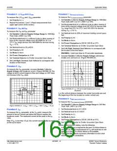
Procedure 8: VTM(Forward and Reverse)
To measure the VTM (Forward and Reverse) parameter:
1. Set Variable Collector Supply Voltage Range to 350 Max
Peak Volts. (400 V on 370)
Figure AN1006.23 (+)VBO = 100 V; (-)VBO = 100 V; (±)IBO < 10 µA
2. Set Horizontal knob to 0.5 V/DIV.
3. Set Vertical knob to 0.5 A/DIV.
4. Set Polarity to (+).
Procedure 6: IBO
To measure the IBO parameter, at the VBO point, measure the
amount of device current just before the device reaches the
breakover mode. The measured current at this point is the IBO
value.
Note: If IBO is less than 10 µA, the current cannot readily be seen
on the curve tracer.
5. Set Mode to Norm.
6. Set Power Dissipation to 220 W (100 W on 577).
7. Set Terminal Selector to Emitter Grounded-Open Base.
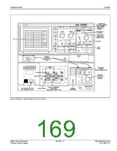
Before continuing with testing, note the following:
•
A Kelvin test fixture is required for this test. If a Kelvin fixture is
not used, an error in measurement of VTM will result due to volt-
age drop in fixture. If a Kelvin fixture is not available,
Figure AN1006.3 shows necessary information to wire a test
fixture with Kelvin Connections.
http://www.teccor.com
+1 972-580-7777
AN1006 - 14
©2002 Teccor Electronics
Thyristor Product Catalog

 TECCOR [ TECCOR ELECTRONICS ]