Application Notes
AN1006
Procedure 11: IH(Forward and Reverse)
For these steps, it is again necessary to connect the Trigger to
MT2 through a 10 Ω resistor. The other connections remain the
same.
To measure the IH (Forward and Reverse) parameter:
1. Set Power Dissipation to 50 W.
2. Set Max Peak Volts to 75 V. (80 V on 370)
3. Set Mode to DC.
Sidacs
The sidac is a bidirectional voltage-triggered switch. Upon appli-
cation of a voltage exceeding the sidac breakover voltage point,
the sidac switches on through a negative resistance region (simi-
lar to a diac) to a low on-state voltage. Conduction continues until
current is interrupted or drops below minimum required holding
current.
To connect the sidac:
1. Connect MT1 to the Emitter Terminal (E).
2. Connect MT2 to the Collector Terminal (C).
4. Set Horizontal knob to 5 V/DIV.
5. Set Vertical knob to approximately 10% of the maximum IH
specified.
To begin testing, perform the following procedures.
Note: Due to large variations of holding current values, the
scale may have to be adjusted to observe holding current.
Procedure 1: (+) VDRM, (+)IDRM, (-)VDRM, (-)IDRM
Note: The (+) and (-) symbols are used to designate the polarity
of MT2 with reference to MT1.
To measure the (+)VDRM, (+)IDRM, (-)VDRM, and (-)IDRM parameter:
1. Set Variable Collector Supply Voltage Range to 1500 Max
Peak Volts.
6. Set Terminal Selector to Emitter Grounded-Open Base.
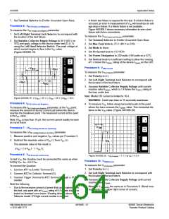
Procedure 12: IH(Forward)
To measure the IH (Forward) parameter:
1. Set Polarity to (+).
2. Set Left-Right Terminal Jack Selector to correspond with
2. Set Horizontal knob to 50 V/DIV.
3. Set Mode to Leakage.
4. Set Polarity to (+).
5. Set Power Dissipation to 2.2 W. (2 W on 370)
6. Set Terminal Selector to Emitter Grounded-Open Base.
the location of the test fixture.
3. Increase Variable Collector Supply Voltage to maximum
position (100).
Note: Depending on the vertical scale being used, the dot
may disappear completely from the screen.
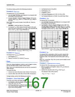
4. Decrease Variable Collector Supply Voltage to the point
where the line on the CRT changes to a dot. The position of
the beginning point of the line, just before the line changes to
a dot, represents the IH value. (Figure AN1006.21)
7. Set Vertical knob to 50 µA/DIV. (Due to leakage mode, the
CRT readout will show 50 nA.)
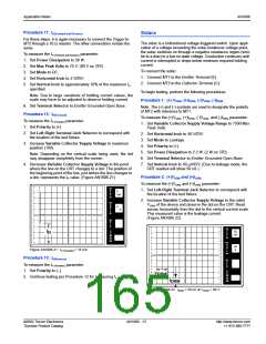
Procedure 2: (+)VDRM and (+)IDRM
To measure the (+)VDRM and (+)IDRM parameter:
PER
V
1. Set Left-Right Terminal Jack Selector to correspond with
5
mA
E
R
the location of the test fixture.
T
DIV
2. Increase Variable Collector Supply Voltage to the rated
PER
H
V
DRM of the device and observe the dot on the CRT. Read
O
5
R
I
V
across horizontally from the dot to the vertical current scale.
This measured value is the leakage current.
(Figure AN1006.22)
Z
DIV
PER
S
T
E
P
PER
V
50
nA
I
E
H
R
()k
DIV
9m
T
DIV
PER
DIV
PER
H
O
50
R
I
Figure AN1006.21 IH (Forward) = 18 mA
V
Z
DIV
Procedure 13: IH(Reverse)
To measure the IH (Reverse) parameter:
PER
S
T
E
P
1. Set Polarity to (–).
2. Continue testing per Procedure 12 for measuring IH (Reverse)
V
()k
DIV
9m
PER
DRM
.
I
DIV
DRM
Figure AN1006.22 IDRM = 50 nA at VDRM = 90 V
©2002 Teccor Electronics
Thyristor Product Catalog
AN1006 - 13
http://www.teccor.com
+1 972-580-7777

 TECCOR [ TECCOR ELECTRONICS ]