AN1006
Application Notes
7. Set Terminal Selector to Emitter Grounded-Open Base.
•
A Kelvin test fixture is required for this test. If a Kelvin fixture is
not used, an error in measurement of VTM will result due to volt-
age drop in fixture. If a Kelvin fixture is not available,
Figure AN1006.3 shows necessary information to wire a test
fixture with Kelvin connections.
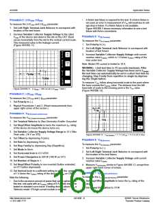
Procedure 5: VBO (Positive and Negative)
To measure the VBO (Positive and Negative) parameter:
1. Set Left-Right Terminal Jack Selector to correspond with
To measure the VTM (Forward and Reverse) parameter:
1. Set Terminal Selector to Emitter Grounded-Open Base.
2. Set Max Peak Volts to 75 V. (80 V on 370)
3. Set Mode to Norm.
the location of the test fixture.
2. Set Variable Collector Supply Voltage to 55 V (65 V on
370) and apply voltage to the device under test (D.U.T.)
using the Left Hand Selector Switch. The peak voltage at
which current begins to flow is the VBO value.
(Figure AN1006.19)
4. Set Horizontal knob to 0.5 V/DIV.
5. Set Power Dissipation to 220 watts (100 watts on a 577).
PER
V
6. Set Vertical knob to a sufficient setting to allow the viewing
50
E
R
A
T
of 1.4 times the IT(RMS) rating of the device IT(peak) on the CRT.
DIV
PER
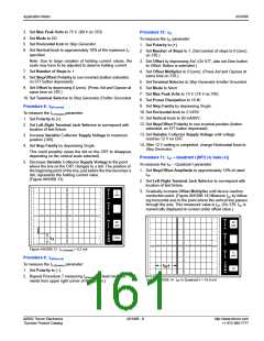
Procedure 9: VTM(Forward)
To measure the VTM (Forward) parameter:
V
H
+I
BO
BO
O
R
I
10
V
Z
DIV
1. Set Polarity to (+).
PER
S
2. Set Left-Right Terminal Jack Selector to correspond with
T
E
P
I
BO
the location of the test fixture.
+V
BO
3. Increase Variable Collector Supply Voltage until current
reaches rated IT(peak), which is 1.4 times the IT(RMS) rating of
the triac under test.
()k
DIV
9m
PER
DIV
Note: Model 370 current is limited to 10 A.
Figure AN1006.19 (+)VBO = 35 V; (-)VBO = 36 V; (±)IBO < 10 A
WARNING: Limit test time to 15 seconds maximum.
Procedure 6: IBO (Positive and Negative)
4. To measure VTM, follow along horizontal scale to the point
where the trace crosses the IT(peak) value. This horizontal dis-
tance is the VTM value. (Figure AN1006.20)
To measure the IBO (Positive and Negative) parameter, at the VBO point,
measure the amount of device current just before the device
reaches the breakover point. The measured current at this point
is the IBO value.
Note: If IBO is less than 10 µA, the current cannot readily be seen
on curve tracer.
PER
V
1
E
R
A
T
DIV
PER
H
V
TM
O
R
I
Procedure 7: ∆VBO (Voltage Breakover Symmetry)
500
mV
Z
To measure the ∆VBO (Voltage Breakover Symmetry) parameter:
1. Measure positive and negative VBO values per Procedure 5.
2. Subtract the absolute value of VBO (-) from VBO (+).
The absolute value of the result is:
DIV
PER
S
T
E
I
P
PK
()k
DIV
9m
PER
DIV
∆VBO = [ I+VBO I - I -VBO I ]
Procedure 8: VTM (Forward and Reverse)
Figure AN1006.20 VTM (Forward) = 1.1 V at IPK = 5.6 A
To test VTM, the Quadrac must be connected the same as when
Procedure 10: VTM(Reverse)
To measure the VTM (Reverse) parameter:
testing VBO, IBO, and ∆VBO
To connect the Quadrac:
.
1. Set Polarity to (–).
1. Connect MT1 to Emitter Terminal (E).
2. Connect MT2 to Collector Terminal (C).
2. Set Left-Right Terminal Jack Selector to correspond with
the location of the test fixture.
3. Connect Trigger Terminal to MT2 Terminal through a 10 Ω
3. Increase Variable Collector Supply Voltage until current
resistor.
reaches rated IT(peak)
.
Note the following:
4. Measure VTM(Reverse) the same as in Procedure 8. (Read mea-
surements from upper right corner of screen).
•
Due to the excessive amount of power that can be generated in
this test, only parts with an IT(RMS) rating of 8 A or less should be
tested on standard curve tracer. If testing devices above 8 A, a
Tektronix model 176 high-current module is required.
http://www.teccor.com
+1 972-580-7777
AN1006 - 12
©2002 Teccor Electronics
Thyristor Product Catalog

 TECCOR [ TECCOR ELECTRONICS ]