Application Notes
AN1006
3. Repeat Procedure 16. (Figure AN1006.17)
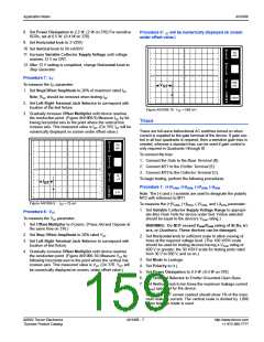
7. Set Vertical knob to ten times the maximum leakage current
(IDRM) specified for the device.
PER
V
Note: The CRT readout should show 1% of the maximum
leakage current. The vertical scale is divided by 1,000 when
the leakage mode is used.
50
mA
E
R
T
DIV
V
GT
PER
H
O
R
Procedure 2: (+)VDRM and (+)IDRM
To measure the (+)VDRM and (+)IDRM parameter:
I
Z
DIV
1. Set Left-Right Terminal Jack Selector to correspond with
PER
S
500
mV
T
the location of the test fixture.
E
P
2. Increase Variable Collector Supply Voltage to the rated
()k
DIV
9m
PER
DIV
V
DRM of the device and observe the dot on the CRT. (Read
100m
across horizontally from the dot to the vertical current scale.)
This measured value is the leakage current.
(Figure AN1006.18)
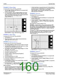
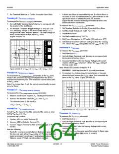
Figure AN1006.17 VGT in Quadrant III = 820 mV
WARNING: Do NOT exceed VDRM/VRRM rating of SCRs, triacs,
Procedure 19: VGT – Quadrant IV [MT2 (-) Gate (+)]
or Quadracs. These devices can be damaged.
To measure the VGT – Quadrant IV parameter:
1. Set Polarity to (–).
PER
V
50
nA
E
R
T
2. Set Step/Offset Polarity by depressing Invert (release but-
DIV
ton on 577).
PER
H
O
50
V
3. Set observed dot to top left corner of CRT grid by turning the
Horizontal position knob. When testing is complete in Quad-
rant IV, return dot to original position.
R
I
Z
DIV
PER
S
4. Repeat Procedure 16.
T
E
P
V
DRM
Quadracs
()k
DIV
9m
PER
DIV
I
DRM
Quadracs are simply triacs with an internally-mounted diac. As
with triacs, Quadracs are bidirectional AC switches which are
gate controlled for either polarity of main terminal voltage.
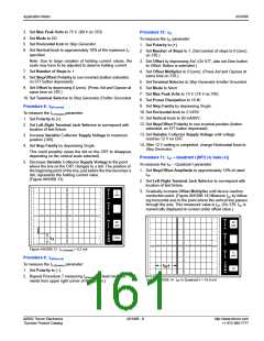
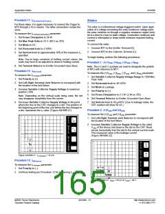
Figure AN1006.18 (+)IDRM = 51 nA at (+)VDRM = 400 V
To connect the Quadrac:
Procedure 3: (-)VDRM and (-)IDRM
1. Connect Trigger to Base Terminal (B).
2. Connect MT1 to Emitter Terminal (E).
3. Connect MT2 to Collector Terminal (C).
To measure the (-)VDRM and (-)IDRM parameter:
1. Set Polarity to (–).
2. Repeat Procedures 1 and 2. (Read measurements from
upper right corner of screen).
To begin testing, perform the following procedures.
Procedure 4: VBO, IBO, ∆VBO
(Quadrac Trigger Diac or Discrete Diac)
To connect the Quadrac:
1. Connect MT1 to Emitter Terminal (E).
2. Connect MT2 to Collector Terminal (C).
Procedure 1: (+)VDRM, (+)IDRM, (-)VDRM, (-)IDRM
Note: The (+) and (-) symbols are used to designate the polarity
of MT2 with reference to MT1.
To measure the (+)VDRM, (+)IDRM, (-)VDRM, and (-)IDRM parameter:
1. Set Variable Collector Supply Voltage Range to appropri-
ate Max Peak Volts for device under test. (Value selected
should be equal to or greater than the device’s VDRM rating).
3. Connect Trigger Terminal to MT2 Terminal through a 10 Ω
resistor.
To measure the VBO, IBO, and ∆VBO parameter:
1. Set Variable Collector Supply Voltage Range to 75 Max
Peak Volts.(80 V on 370)
2. Set Horizontal knob to 10 V/DIV.
3. Set Vertical knob to 50 µA/DIV.
4. Set Polarity to AC.
2. Set Horizontal knob to sufficient scale to allow viewing of
trace at the required voltage level. (The 100 V/DIV scale
should be used for testing devices having a VDRM rating of
600 V or greater; the 50 V/DIV scale for testing parts rated
from 300 V to 500 V, and so on).
3. Set Mode to Leakage.
4. Set Polarity to (+).
5. Set Mode to Norm.
6. Set Power Dissipation to 0.5 W. (0.4 W on 370)
5. Set Power Dissipation to 0.5 W. (0.4 W on 370)
6. Set Terminal Selector to Emitter Grounded-Open Base.
©2002 Teccor Electronics
Thyristor Product Catalog
AN1006 - 11
http://www.teccor.com
+1 972-580-7777

 TECCOR [ TECCOR ELECTRONICS ]