AN1006
Application Notes
9. Set Step Family by depressing Single.
10. Set Horizontal knob to 2 V/DIV.
Procedure 12: IGT – Quadrant II [MT2 (+) Gate (-)]
To measure the IGT – Quadrant II parameter:
11. Set Step/Offset Polarity to non-inverted position (button
1. Set Step/Offside Polarity by depressing Invert (release but-
extended, on 577 button depressed).
ton on 577).
12. Set Current Limit to 500 mA (not available on 577).
2. Set Polarity to (+).
3. Set observed dot to bottom right corner of CRT grid by turn-
ing the horizontal position knob. When Quadrant II testing is
complete, return dot to original position.
13. Increase Variable Collector Supply Voltage until voltage
reaches 12 V on CRT.
14. After 12 V setting is complete, change Horizontal knob to
Step Generator.
4. Repeat Procedure 11.
Procedure 16: VGT – Quadrant I [MT2 (+) Gate (+)]
To measure the VGT – Quadrant I parameter:
1. Set Step/Offset Amplitude to 20% of rated VGT.
Procedure 13: IGT – Quadrant III [MT2 (-) Gate (-)]
To measure the IGT – Quadrant III parameter:
1. Set Polarity to (–).
2. Set Left-Right Terminal Jack Selector to correspond with
2. Set Step/Offset Polarity to non-inverted position (button
location of test fixture.
extended, on 577 button depressed).
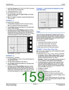
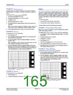
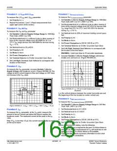
3. Gradually increase Offset Multiplier until device reaches
conduction point. (Figure AN1006.16) Measure VGT by fol-
lowing horizontal axis to the point where the vertical line
passes through the axis. This measured value will be VGT.
(On 370, VGT will be numerically displayed on screen under
offset value.)
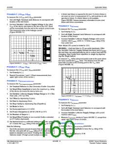
3. Repeat Procedure 11. (Figure AN1006.15)
PER
V
50
mA
E
R
I
T
GT
DIV
PER
H
O
R
I
PER
V
Z
DIV
50
mA
E
R
T
PER
DIV
S
5
mA
T
PER
H
O
R
E
P
I
V
()k
DIV
9m
PER
DIV
GT
Z
DIV
10
PER
S
500
mV
T
E
P
Figure AN1006.15 IGT in Quadrant III = 27 mA
()k
DIV
9m
PER
DIV
Procedure 14: IGT – Quadrant IV [MT2 (-) Gate (+)]
100m
To measure the IGT – Quadrant IV parameter:
1. Set Polarity to (–).
Figure AN1006.16 VGT in Quadrant I = 780 mV
2. Set Step/Offset Polarity by depressing Invert (release but-
Procedure 17: VGT – Quadrant II [MT2 (+) Gate (-)]
ton on 577).
To measure the VGT – Quadrant II parameter:
3. Set observed dot to top left corner of CRT grid by turning the
Horizontal position knob. When Quadrant IV testing is com-
plete, return dot to original position.
1. Set Step/Offset Polarity by depressing Invert (release but-
ton on 577).
4. Repeat Procedure 11.
2. Set Polarity to (+).
3. Set observed dot to bottom right corner of CRT grid by turn-
ing the horizontal position knob. When Quadrant II testing is
complete, return dot to original position.
Procedure 15: VGT
To measure the VGT parameter:
1. Set Polarity to (+).
4. Repeat Procedure 16.
2. Set Number of Steps to 1. (Set steps to 0 (zero) on 370.)
Procedure 18: VGT – Quadrant III [MT2 (-) Gate (-)]
To measure the VGT – Quadrant III parameter:
3. Set Offset by depressing Aid. (On 577, also set 0 (zero) but-
ton to Offset. Button is extended.)
1. Set Polarity to (–).
4. Set Offset Multiplier to 0 (zero). (Press Aid and Oppose at
same time on 370.)
2. Set Step/Offset Polarity to non-inverted position (button
extended, on 577 button depressed).
5. Set Terminal Selector to Step Generator-Emitter Grounded.
6. Set Mode to Norm.
7. Set Max Peak Volts to 15 V. (16 V on 370)
8. Set Power Dissipation to 10 W.
http://www.teccor.com
+1 972-580-7777
AN1006 - 10
©2002 Teccor Electronics
Thyristor Product Catalog

 TECCOR [ TECCOR ELECTRONICS ]