Application Notes
AN1006
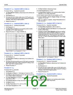
3. Set Max Peak Volts to 75 V. (80 V on 370)
4. Set Mode to DC.
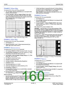
Procedure 10: IGT
To measure the IGT parameter:
5. Set Horizontal knob to Step Generator.
1. Set Polarity to (+).
6. Set Vertical knob to approximately 10% of the maximum IH
2. Set Number of Steps to 1. (Set number of steps to 0 (zero)
specified.
on 370.)
Note: Due to large variation of holding current values, the
scale may have to be adjusted to observe holding current.
3. Set Offset by depressing Aid. (On 577, also set Zero button
to Offset. Button is extended.)
7. Set Number of Steps to 1.
4. Set Offset Multiplier to 0 (zero). (Press Aid and Oppose at
same time on 370.)
8. Set Step/Offset Polarity to non-inverted (button extended,
on 577 button depressed).
5. Set Terminal Selector to Step Generator-Emitter Grounded.
6. Set Mode to Norm.
7. Set Max Peak Volts to 15 V. (16 V on 370)
8. Set Power Dissipation to 10 W.
9. Set Offset by depressing 0 (zero). (Press Aid and Oppose at
same time on 370.)
10. Set Terminal Selector to Step Generator-Emitter Grounded.
9. Set Step Family by depressing Single.
10. Set Horizontal knob to 2 V/DIV.
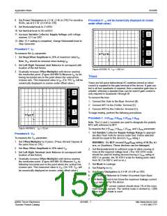
Procedure 8: IH(Forward)
To measure the IH (Forward) parameter:
11. Set Vertical knob to 50 mA/DIV.
1. Set Polarity to (+).
12. Set Step/Offset Polarity to non-inverted position (button
2. Set Left-Right Terminal Jack Selector to correspond with
extended, on 577 button depressed).
location of test fixture.
13. Set Variable Collector Supply Voltage until voltage
3. Increase Variable Collector Supply Voltage to maximum
reaches 12 V on CRT.
position (100).
14. After 12 V setting is completed, change Horizontal knob to
4. Set Step Family by depressing Single.
Step Generator.
This could possibly cause the dot on the CRT to disappear,
depending on the vertical scale selected).
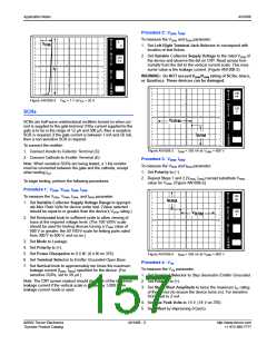
Procedure 11: IGT – Quadrant I [MT2 (+) Gate (+)]
To measure the IGT – Quadrant I parameter:
5. Decrease Variable Collector Supply Voltage to the point
where the line on the CRT changes to a dot. The position of
the beginning point of the line, just before the line becomes a
dot, represents the holding current value.
1. Set Step/Offset Amplitude to approximately 10% of rated
IGT.
(Figure AN1006.13)
2. Set Left-Right Terminal Jack Selector to correspond with
location of test fixture.
PER
V
3. Gradually increase Offset Multiplier until device reaches
conduction point. (Figure AN1006.14) Measure IGT by follow-
ing horizontal axis to the point where the vertical line passes
through the axis. This measured value is IGT. (On 370, IGT is
numerically displayed on screen under offset value.)
5
mA
E
R
T
DIV
PER
H
O
R
I
Z
DIV
PER
V
PER
S
50
mA
50
mA
E
T
R
E
P
T
DIV
PER
H
()k
DIV
9m
PER
DIV
O
R
100m
I
H
I
Z
DIV
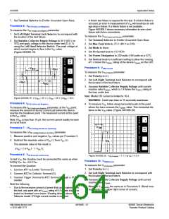
Figure AN1006.13 IH (Forward) = 8.2 mA
PER
S
5
mA
T
E
P
Procedure 9: IH(Reverse)
()k
DIV
9m
PER
DIV
To measure the IH (Reverse) parameter:
1. Set Polarity to (–).
I
GT
10
2. Repeat Procedure 7 measuring IH(Reverse). (Read measure-
ments from upper right corner of the screen.)
Figure AN1006.14 IGT in Quadrant I = 18.8 mA
©2002 Teccor Electronics
Thyristor Product Catalog
AN1006 - 9
http://www.teccor.com
+1 972-580-7777

 TECCOR [ TECCOR ELECTRONICS ]