Application Notes
AN1006
8. Set Power Dissipation to 2.2 W. (2 W on 370) For sensitive
SCRs, set at 0.5 W. (0.4 W on 370)
9. Set Horizontal knob to 2 V/DIV.
10. Set Vertical knob to 50 mA/DIV.
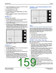
Procedure 9: GT will be numerically displayed on screen
under offset value.)
PER
V
50
mA
E
R
11. Increase Variable Collector Supply Voltage until voltage
T
DIV
reaches 12 V on CRT.
PER
H
12. After 12 V setting is completed, change Horizontal knob to
O
R
Step Generator.
I
Z
DIV
Procedure 7: IGT
To measure the IGT parameter:
PER
S
200
mV
T
E
P
V
GT
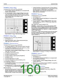
1. Set Step/Offset Amplitude to 20% of maximum rated IGT.
Note: RGK should be removed when testing IGT.
()k
DIV
9m
PER
DIV
250m
2. Set Left-Right Terminal Jack Selector to correspond with
location of the test fixture.
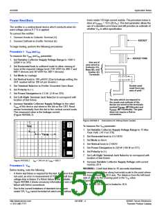
Figure AN1006.10 VGT = 580 mV
3. Gradually increase Offset Multiplier until device reaches
the conduction point. (Figure AN1006.9) Measure IGT by fol-
lowing horizontal axis to the point where the vertical line
crosses axis. This measured value is IGT. (On 370, IGT will be
numerically displayed on screen under offset value.)
Triacs
Triacs are full-wave bidirectional AC switches turned on when
current is supplied to the gate terminal of the device. If gate con-
trol in all four quadrants is required, then a sensitive gate triac is
needed, whereas a standard triac can be used if gate control is
only required in Quadrants I through III.
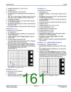
PER
V
50
mA
E
R
T
DIV
To connect the triac:
PER
H
O
R
1. Connect the Gate to the Base Terminal (B).
2. Connect MT1 to the Emitter Terminal (E).
3. Connect MT2 to the Collector Terminal (C).
To begin testing, perform the following procedures.
I
Z
DIV
PER
S
10
A
T
E
P
I
GT
Procedure 1: (+)VDRM, (+)IDRM, (-)VDRM, (-)IDRM
Note: The (+) and (-) symbols are used to designate the polarity
MT2 with reference to MT1.
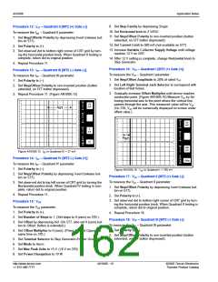
()k
DIV
9m
PER
DIV
5
K
Figure AN1006.9 IGT = 25 µA
To measure the (+)VDRM, (+)IDRM, (-)VDRM, and (-)IDRM parameter:
1. Set Variable Collector Supply Voltage Range to appropri-
ate Max Peak Volts for device under test. (Value selected
should be equal to the device’s VDRM rating.)
Procedure 8: VGT
To measure the VGT parameter:
1. Set Offset Multiplier to 0 (zero). (Press Aid and Oppose at
WARNING: Do NOT exceed VDRM/VRRM rating of SCRs, tri-
the same time on 370.)
acs, or Quadracs. These devices can be damaged.
2. Set Step Offset Amplitude to 20% rated VGT.
2. Set Horizontal knob to sufficient scale to allow viewing of
trace at the required voltage level. (The 100 V/DIV scale
should be used for testing devices having a VDRM rating of
600 V or greater; the 50 V/DIV scale for testing parts rated
from 30 V to 500 V, and so on.)
3. Set Mode to Leakage.
4. Set Polarity to (+).
3. Set Left-Right Terminal Jack Selector to correspond with
location of test fixture.
4. Gradually increase Offset Multiplier until device reaches
the conduction point. (Figure AN1006.10) Measure VGT by
following horizontal axis to the point where the vertical line
crosses axis. This measured value is VGT. (On 370, V will
GT
be numerically displayed on screen, under offset value.)
5. Set Power Dissipation to 0.5 W. (0.4 W on 370)
6. Set Terminal Selector to Emitter Grounded-Open Base.
7. Set Vertical knob to ten times the maximum leakage current
(IDRM) specified for the device.
Note: The CRT screen readout should show 1% of the maxi-
mum leakage current. The vertical scale is divided by 1,000
when leakage mode is used.
©2002 Teccor Electronics
Thyristor Product Catalog
AN1006 - 7
http://www.teccor.com
+1 972-580-7777

 TECCOR [ TECCOR ELECTRONICS ]