Application Notes
AN1006
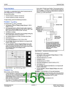
Procedure 2: VDRM, IDRM
PER
V
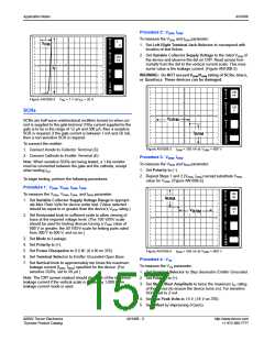
To measure the VDRM and IDRM parameter:
2
E
V
R
FM
A
1. Set Left-Right Terminal Jack Selector to correspond with
T
DIV
location of test fixture.
PER
H
2. Set Variable Collector Supply Voltage to the rated VDRM of
the device and observe the dot on CRT. Read across hori-
zontally from the dot to the vertical current scale. This mea-
sured value is the leakage current. (Figure AN1006.5)
O
R
500
mV
I
Z
DIV
I
T
PER
S
T
E
WARNING: Do NOT exceed VDRM/VRRM rating of SCRs, triacs,
P
or Quadracs. These devices can be damaged.
()k
DIV
9m
PER
DIV
PER
V
100
nA
E
R
T
DIV
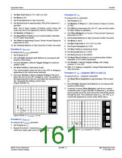
Figure AN1006.4 VFM = 1 V at IPK = 20 A
PER
H
O
100
V
R
I
SCRs
Z
DIV
V
DRM
PER
S
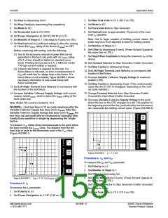
SCRs are half-wave unidirectional rectifiers turned on when cur-
rent is supplied to the gate terminal. If the current supplied to the
gate is to be in the range of 12 µA and 500 µA, then a sensitive
SCR is required; if the gate current is between 1 mA and 50 mA,
then a non-sensitive SCR is required.
T
E
P
I
DRM
()k
DIV
9m
PER
DIV
To connect the rectifier:
1. Connect Anode to Collector Terminal (C).
2. Connect Cathode to Emitter Terminal (E).
Figure AN1006.5 IDRM = 350 nA at VDRM = 600 V
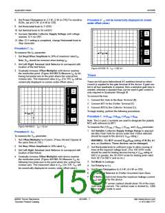
Procedure 3: VRRM, IRRM
To measure the VRRM and IRRM parameter:
1. Set Polarity to (–).
Note: When sensitive SCRs are being tested, a 1 kΩ resistor
must be connected between the gate and the cathode, except
when testing I
.
GT
2. Repeat Steps 1 and 2 (VDRM, IDRM) except substitute VRRM
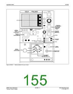
To begin testing, perform the following procedures.
value for VDRM. (Figure AN1006.6)
.
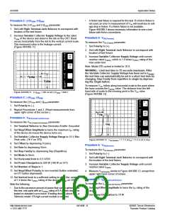
Procedure 1: VDRM, VRRM, IDRM, IRRM
To measure the VDRM, VRRM, IDRM, and IRRM parameter:
1. Set Variable Collector Supply Voltage Range to appropri-
ate Max Peak Volts for device under test. (Value selected
should be equal to or greater than the device’s VDRM rating.)
PER
V
100
nA
E
R
T
I
RRM
DIV
PER
H
O
R
100
V
V
RRM
I
Z
DIV
2. Set Horizontal knob to sufficient scale to allow viewing of
trace at the required voltage level. (The 100 V/DIV scale
should be used for testing devices having a VDRM value of
600 V or greater; the 50 V/DIV scale for testing parts rated
from 300 V to 500 V, and so on.)
3. Set Mode to Leakage.
4. Set Polarity to (+).
PER
S
T
E
P
()k
DIV
9m
PER
DIV
5. Set Power Dissipation to 0.5 W. (0.4 W on 370)
6. Set Terminal Selector to Emitter Grounded-Open Base.
7. Set Vertical knob to approximately ten times the maximum
leakage current (IDRM, IRRM) specified for the device. (For
sensitive SCRs, set to 50 µA.)
Note: The CRT screen readout should show 1% of the maximum
leakage current if the vertical scale is divided by 1,000 when
leakage current mode is used.
Figure AN1006.6 IRRM = 340 nA at VRRM = 600 V
Procedure 4: VTM
To measure the VTM parameter:
1. Set Terminal Selector to Step Generator-Emitter Grounded.
2. Set Polarity to (+).
3. Set Step/Offset Amplitude to twice the maximum IGT rating
of the device (to ensure the device turns on). For sensitive
SCRs, set to 2 mA.
4. Set Max Peak Volts to 15 V. (16 V on 370)
5. Set Offset by depressing 0 (zero).
©2002 Teccor Electronics
Thyristor Product Catalog
AN1006 - 5
http://www.teccor.com
+1 972-580-7777

 TECCOR [ TECCOR ELECTRONICS ]