AN1006
Application Notes
tronix model 176 high-current module. The procedure below is
Power Rectifiers
done at I
= 10 A (20 APK). This test parameter allows the
T(RMS)
use of a standard curve tracer and still provides an estimate of
whether VFM is within specification.
The rectifier is a unidirectional device which conducts when for-
ward voltage (above 0.7 V) is applied.
To connect the rectifier:
1. Connect Anode to Collector Terminal (C).
2. Connect Cathode to Emitter Terminal (E).
SOCKET
To begin testing, perform the following procedures.
Procedure 1: VRRM and IRM
To measure the VRRM and IRM parameter:
1. Set Variable Collector Supply Voltage Range to 1500 V.
(2000 V on 370)
2. Set Horizontal knob to sufficient scale to allow viewing of
trace at the required voltage level (100 V/DIV for 400 V and
600 V devices and 50 V/DIV for 200 V devices).
3. Set Mode to Leakage.
SOCKET PINS
One set of
pins wired to
Collector (C),
Base (B), and
Emitter (E)
Terminals
4. Set Vertical knob to 100 µA/DIV. (Due to leakage setting, the
CRT readout will be 100 nA per division.)
Socket used
must have two
sets of pins
5. Set Terminal Selector to Emitter Grounded-Open Base.
6. Set Polarity to (–).
7. Set Power Dissipation to 2.2 W. (2 W on 370)
8. Set Left-Right Terminal Jack Selector to correspond with
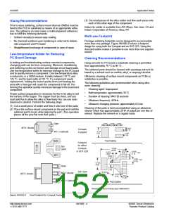
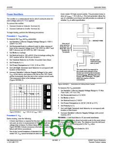
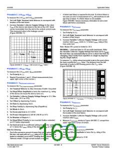
The pins which correspond to
the anode and cathode of the
device are wired to the terminals
marked CSENSE (MT2/Anode) and
ESENSE (MT1/Cathode). The gate
does not require a Kelvin
connection.
location of test fixture.
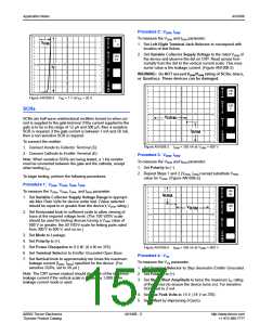
9. Increase Variable Collector Supply Voltage to the rated
V
RRM of the device and observe the dot on the CRT. Read
across horizontally from the dot to the vertical current scale.
This measured value is the leakage current.
(Figure AN1006.2)
Figure AN1006.3 Instructions for Wiring Kelvin Socket
To measure the VFM parameter:
PER
V
100
nA
E
R
I
T
RM
DIV
1. Set Variable Collector Supply Voltage Range to 15 Max
Peak Volts. (16 V on 370)
2. Set Horizontal knob to 0.5 V/DIV.
3. Set Mode to Norm.
4. Set Vertical knob to 2 A/DIV.
5. Set Power Dissipation to 220 W (100 W on 577).
6. Set Polarity to (+).
PER
H
O
100
V
R
V
RRM
I
Z
DIV
PER
S
T
E
P
()k
DIV
9m
PER
DIV
7. Set Left-Right Terminal Jack Selector to correspond with
location of test fixture.
Figure AN1006.2
IRM = 340 nA at VRRM = 600 V
8. Increase Variable Collector Supply Voltage until current
reaches 20 A.
Procedure 2: VFM
Before testing, note the following:
WARNING: Limit test time to 15 seconds maximum.
To measure VFM, follow along horizontal scale to the point where
the trace crosses the 20 A axis. The distance from the left-hand
side of scale to the crossing point is the VFM value.
(Figure AN1006.4)
•
A Kelvin test fixture is required for this test. If a Kelvin fixture is
not used, an error in measurement of VFM will result due to
voltage drop in fixture. If a Kelvin fixture is not available,
Figure AN1006.3 shows necessary information to wire a test
fixture with Kelvin connections.
Note: Model 370 current is limited to 10 A.
•
Due to the current limitations of standard curve tracer
model 576, V cannot be tested at rated current without a Tek-
FM
http://www.teccor.com
+1 972-580-7777
AN1006 - 4
©2002 Teccor Electronics
Thyristor Product Catalog

 TECCOR [ TECCOR ELECTRONICS ]