SIDACtor Soldering Recommendations
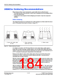
Wave Soldering
Another common method for soldering components to a PCB is wave soldering. After
fluxing the PCB, an adhesive is applied to the respective footprints so that components can
be glued in place. Once the adhesive has cured, the board is pre-heated and then placed in
contact with a molten wave of solder which has a temperature between 240 °C and 260 °C
and permanently affixes the component to the PCB. (Figure 5.8 and Figure 5.10)
Although a popular method of soldering, wave soldering does have drawbacks:
•
•
•
A double pass is often required to remove excess solder.
Solder bridging and shadows begin to occur as board density increases.
Wave soldering uses the sharpest thermal gradient.
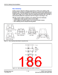
Apply glue
Place component
Cure glue
Wave solder
Screen print glue
Figure 5.9 Wave Soldering Surface Mount Components Only
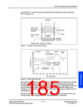
PC board
Insert
leaded
components
Turn over the
PC board
Apply
glue
Place
SMDs
Cure
glue
Turn over the
PC board
Wave solder
Figure 5.10 Wave Soldering Surface Mount and Leaded Components
http://www.teccor.com
+1 972-580-7777
5 - 24
© 2002 Teccor Electronics
®
SIDACtor Data Book and Design Guide

 TECCOR [ TECCOR ELECTRONICS ]