CATV Line Amplifiers/Power Inserters SIDACtor Device
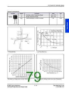
Thermal Considerations
Package
Symbol
TJ
TS
Parameter
Operating Junction Temperature Range
Storage Temperature Range
Value
-40 to +150
-65 to +150
100
Unit
°C
°C
2
TO-218
TC
Maximum Case Temperature
°C
R
R
Thermal Resistance: Junction to Case
Thermal Resistance: Junction to Ambient
1.7
56
°C/W
°C/W
ꢀJC *
ꢀJA
3
(No
2
1
Connection)
* RꢀJC rating assumes the use of a heat sink and on state mode for extended time at 25 A, with average power dissipation of 29.125 W.
+I
tr = rise time to peak value
td = decay time to half value
IT
Peak
Value
100
50
0
IS
IH
Waveform = tr x td
IDRM
-V
+V
Half Value
VDRM
VT
VS
tr
td
0
t – Time (µs)
-I
V-I Characteristics
tr x td Pulse Wave-form
14
12
10
8
2.0
1.8
1.6
1.4
1.2
1.0
0.8
0.6
6
4
25 ˚C
25 ˚C
2
0
-4
-6
0.4
-40 -20
0
20 40 60 80 100 120 140 160
Case Temperature (TC) – ˚C
-8
-40 -20
0
20 40 60 80 100 120 140 160
Junction Temperature (TJ) – ˚C
Normalized VS Change versus Junction Temperature
Normalized DC Holding Current versus Case Temperature
© 2002 Teccor Electronics
2 - 65
http://www.teccor.com
+1 972-580-7777
®
SIDACtor Data Book and Design Guide

 TECCOR [ TECCOR ELECTRONICS ]