High Speed Transmission Equipment
exceed 10 mAPK at any time. As an alternative to carrying out this test
on the complete equipment or device, the test may be carried out
separately on components, subassemblies, and simulated circuits,
outside the unit, provided that the test results would be representative of
the results of testing the complete unit.
Regenerator
COT
F1250T
P1800SC MC
P1800SC MC
F1250T
F1250T
RX
TX
P0300SA
P0640SC MC
T1
Transceiver
T1
Transceiver
Power
Source
F1250T
P1800SC MC
P1800SC MC
F1250T
F1250T
P0640SC MC
RX
TX
P0300SA
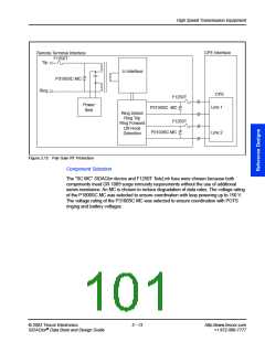
Figure 3.17 T1/E1 Protection
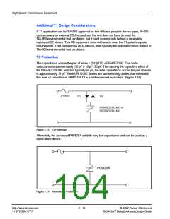
The peak voltage for 120 V rms is 169.7 V. The minimum stand-off voltage for the P1800 is
170 V, therefore, the P1800SC MC will pass the test in Section 4.4.5.2 by not allowing
10 mA of current to flow during the application of this test voltage.
For the transceiver side of the coupling transformer, additional overvoltage protection is
shown in Figure 3.17 using the P0300SA SIDACtor device. When an earth ground
connection is not used, only metallic protection is required. Metallic protection is satisfied
using a single P0640SC MC SIDACtor device across Tip and Ring and a single F1250T
TeleLink fuse on either Tip or Ring.
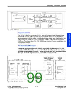
Component Selection
The “SC MC” SIDACtor device and F1250T TeleLink fuse were chosen because these
components meet GR 1089 surge immunity requirements without the use of additional
series resistance. An MC is chosen to reduce degradation of data rates. The voltage rating
of the P1800SC MC was selected to ensure loop powering up to 150 V. The voltage rating
of the P0640SC MC was selected to ensure coordination with varying voltage signals.
© 2002 Teccor Electronics
3 - 15
http://www.teccor.com
+1 972-580-7777
®
SIDACtor Data Book and Design Guide

 TECCOR [ TECCOR ELECTRONICS ]