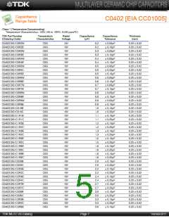
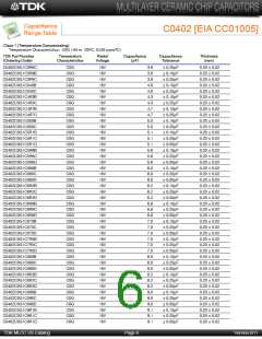
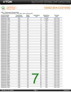
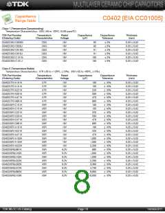
C Series
General Application
Type: C0402, C0603, C1005, C1608,
C2012, C3216, C3225, C4532, C5750
• Electronics equipment
• Mobile communications equipment
• Office automation equipment
• Automotive electronics
• Test and measurement equipment
• Hybrid ICs, etc.
• Decoupling
• Smoothing
• Charge pump
•
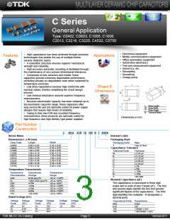
High capacitance has been achieved through precision
Features
Applications
technologies that enable the use of multiple thinner
ceramic dielectric layers.
•
A monolithic structure ensures superior mechanical
strength and reliability.
High-accuracy automatic mounting is facilitated through
the maintenance of very precise dimensional tolerances.
Composed of only ceramics and metals, these
•
•
capacitors provide extremely dependable performance,
exhibiting virtually no degradation even when subjected to
temperature extremes.
•
Low stray capacitance ensures high conformity with
Shape &
Dimensions
nominal values, thereby simplifying the circuit design
process.
•
Low residual inductance assures superior frequency
characteristics.
Because electrostatic capacity has been obtained up to
•
the electrolytic capacitor range, these capacitors offer
long service life and are optimally suited for power supply
designs that require high levels of reliability.
L
W
T
Body Length
Body Width
Body Height
Terminal Width
B
•
Owing to their low ESR and excellent frequency
characteristics, these products are optimally suited for
high frequency and high-density type power supplies.
Dimensions in mm
Part Number
Construction
C
2012 X7R 1E 105 K T XXXX
Series Name
Dimensions L x W (mm)
Internal Codes
Packaging Style
Packaging Code
T
Capacitance Tolerance
Tolerance Code
W
B
C
D
E
G
J
K
M
Z
Case Code
C0402
C0603
C1005
C1608
C2012
C3216
C3225
C4532
C5750
Length
Width
Style
Tape & Reel
0.40 ± 0.02
0.60 ± 0.03
1.00 ± 0.05
1.60 ± 0.10
2.00 ± 0.20
3.20 ± 0.20
3.20 ± 0.40
4.50 ± 0.40
5.70 ± 0.40
0.20 ± 0.02
0.30 ± 0.03
0.50 ± 0.05
0.80 ± 0.10
1.25 ± 0.20
1.60 ± 0.20
2.50 ± 0.30
3.20 ± 0.40
5.00 ± 0.40
Tolerance
± 0.05 pF
± 0.10 pF
± 0.25 pF
± 0.50 pF
± 0.20 pF
± 2%
± 5%
± 10%
± 20%
+80-20%
Temperature Characteristic
Temperature
Characteristics
Capacitance
Change
Temperature
Range
-55 to +125ºC
C0G
SL
0±30 ppm/ºC
+350/-1000 ppm/ºC -25 to +85ºC
Nominal Capacitance (pF)
The capacitance is expressed in three digit
codes and in units of pico Farads (pF). The first
and second digits identify the first and second
significant figures of the capacitance. The third
digit identifies the multiplier. R designates a
decimal point.
X5R
X6S
X7R
X7S
Y5V
±15%
+22%
±15%
±22%
-55 to +85ºC
-55 to +105ºC
-55 to +125ºC
-55 to +125ºC
-33 to +85ºC
+22/-82%
Rated Voltage (DC)
Voltage
Code
0G
0J
Voltage
(DC)
4V
6.3V
10V
Voltage
Code
1C
1E
1V
Voltage
(DC)
16V
25V
35V
Voltage
Code
1H
Voltage
(DC)
50V
Capacitance Code Capacitance
0R5
010
102
105
0.5pF
1pF
1,000pF (1nF)
1,000,000pF (1µF)
1A
TDK MLCC US Catalog
Page 5
Version B11

 TDK [ TDK ELECTRONICS ]