C2510Fx / CC2511Fx
14.11 Forward Error Correction with Interleaving
14.11.1 Forward Error Correction (FEC)
sensitivity. In other words, the improved
reception by using FEC and the degraded
sensitivity from a higher receiver bandwidth
will be counteracting factors.
CC2510Fx/CC2511Fx has built in support for
Forward Error Correction (FEC). To enable
this option, set MDMCFG1.FEC_ENto 1. FEC is
only supported in fixed packet length mode
(PKTCTRL0.LENGTH_CONFIG=0). FEC is
employed on the data field and CRC word in
order to reduce the gross bit error rate when
14.11.2
Interleaving
Data received through radio channels will
often experience burst errors due to
interference and time-varying signal strengths.
In order to increase the robustness to errors
spanning multiple bits, interleaving is used
when FEC is enabled. After de-interleaving, a
continuous span of errors in the received
stream will become single errors spread apart.
operating
near
the
sensitivity
limit.
Redundancy is added to the transmitted data
in such a way that the receiver can restore the
original data in the presence of some bit
errors.
The use of FEC allows correct reception at a
lower SNR, thus extending communication
range. Alternatively, for a given SNR, using
FEC decreases the bit error rate (BER). As the
packet error rate (PER) is related to BER by:
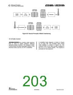
CC2510Fx/CC2511Fx employs matrix interleaving,
which is illustrated in Figure 52. The on-chip
interleaving and de-interleaving buffers are 4 x
4 matrices. In the transmitter, the data bits
from the rate ½ convolutional coder are written
into the rows of the matrix, whereas the bit
sequence to be transmitted is read from the
columns of the matrix. Conversely, in the
receiver, the received symbols are written into
the columns of the matrix, whereas the data
passed onto the convolutional decoder is read
from the rows of the matrix.
PER = 1− (1− BER)packet _ length
,
a lower BER can be used to allow longer
packets, or a higher percentage of packets of
a given length, to be transmitted successfully.
Finally, in realistic ISM radio environments,
transient and time-varying phenomena will
produce occasional errors even in otherwise
good reception conditions. FEC will mask such
errors and, combined with interleaving of the
coded data, even correct relatively long
periods of faulty reception (burst errors).
When FEC and interleaving is used at least
one extra byte is required for trellis
termination. In addition, the amount of data
transmitted over the air must be a multiple of
the size of the interleaver buffer (two bytes).
The packet control hardware therefore
automatically inserts one or two extra bytes at
the end of the packet, so that the total length
of the data to be interleaved is an even
number. Note that these extra bytes are
invisible to the user, as they are removed
before the received packet enters the RFD
data register.
The
FEC
scheme
adopted
for
CC2510Fx/CC2511Fx is convolutional coding, in
which n bits are generated based on k input
bits and the m most recent input bits, forming
a code stream able to withstand a certain
number of bit errors between each coding
state (the m-bit window).
The convolutional coder is a rate 1/2 code with
a constraint length of m=4. The coder codes
one input bit and produces two output bits;
hence, the effective data rate is halved. I.e. to
transmit at the same effective data rate when
using FEC, it is necessary to use twice as high
over-the-air data rate. This will require a higher
receiver bandwidth, and thus reduce
When FEC and interleaving is used the
minimum data payload is 2 bytes.
SWRS055D
Page 202 of 243

 TAOS [ TEXAS ADVANCED OPTOELECTRONIC SOLUTIONS ]