C2510Fx / CC2511Fx
(e.g. 10 kBaud), can be realized using a higher
over-the-air data rate. Buffering the data and
transmitting in bursts at high data rate (e.g.
500 kBaud) will reduce the time in active
mode, and hence also reduce the average
current consumption significantly. Reducing
the time in active mode will reduce the
likelihood of collisions with other systems, e.g.
WLAN.
Thus, higher data rates can be transmitted in
the same bandwidth using GFSK.
14.17.7
Low Cost Systems
A differential antenna will eliminate the need
for a balun (see Figure 10, Figure 11, and
Figure 12). The CC25XX Folded Dipole
reference design [3] contains schematics and
layout files for a CC2500EM with a folded
dipole PCB antenna. This antenna design can
also be used by the CC2510Fx/CC2511Fx to
provide a low cost system. Please see DN004
[10] for more details on this design.
14.17.5 Crystal Drift Compensation
The CC2510Fx/CC2511Fx has
a
very fine
frequency resolution (see Table 16). This
feature can be used to compensate for
frequency offset and drift.
A HC-49 type SMD crystal is used in the
CC2510EM reference design [1]. Note that the
crystal package strongly influences the price.
In a size constrained PCB design a smaller,
but more expensive, crystal may be used.
The frequency offset between an ‘external’
transmitter and the receiver is measured in the
CC2510Fx/CC2511Fx and can be read back from
the FREQEST status register as described in
Section 14.7.1. The measured frequency offset
can be used to calibrate the frequency using
the ‘external’ transmitter as the reference. That
is, the received signal of the device will match
the receiver’s channel filter better. In the same
way the centre frequency of the transmitted
signal will match the ‘external’ transmitter’s
signal.
14.17.8
Battery Operated Systems
In low power applications, PM2 or PM3 should
be used when the CC2510Fx/CC2511Fx is not
active. The Sleep Timer can be used in PM2.
14.17.9
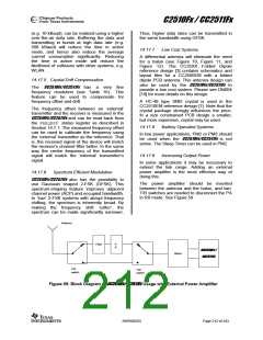
Increasing Output Power
In some applications it may be necessary to
extend the link range. Adding an external
power amplifier is the most effective way of
doing this.
14.17.6
Spectrum Efficient Modulation
CC2510Fx/CC2511Fx also has the possibility to
use Gaussian shaped 2-FSK (GFSK). This
spectrum-shaping feature improves adjacent
channel power (ACP) and occupied bandwidth.
In ‘true’ 2-FSK systems with abrupt frequency
shifting, the spectrum is inherently broad. By
making the frequency shift ‘softer’, the
spectrum can be made significantly narrower.
The power amplifier should be inserted
between the antenna and the balun, and two.
T/R switches are needed to disconnect the PA
in RX mode. See Figure 59
Antenna
Filter
P
A
CC2510Fx /
Balun
CC2511Fx
T/R
switch
T/R
switch
Figure 59: Block Diagram of CC2510Fx/CC2511Fx Usage with External Power Amplifier
SWRS055D
Page 212 of 243

 TAOS [ TEXAS ADVANCED OPTOELECTRONIC SOLUTIONS ]