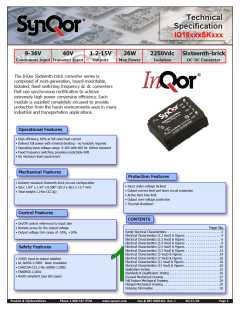
Technical
Specification
IQ18xxxSKxxx
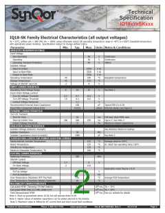
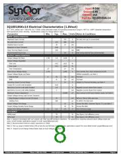
IQ18-SK Family Electrical Characteristics (all output voltages)
Ta = 25°C, airflow rate = 300 LFM, Vin = 18Vdc unless otherwise noted; full operating temperature range is -40°C to +100°C baseplate temperature
with appropriate power derating. Specifications subject to change without notice.
Parameter
ABSOLUTE MAXIMUM RATINGS
Min.
Typ.
Max. Units Notes & Conditions
Input Voltage
Non-Operating
Operating
Operating Transient Protection
Isolation Voltage
50
36
40
V
V
V
Continuous
Continuous
100ms
Input to Output
Input to Base-Plate
Output to Base-Plate
Operating Temperature
Storage Temperature
Voltage at ON/OFF input pin
INPUT CHARACTERISTICS
Operating Input Voltage Range
Input Under-Voltage Lockout
Turn-On Voltage Threshold
Turn-Off Voltage Threshold
Lockout Voltage Hysteresis
Recommended External Input Capacitance
Input Filter Component Values (L\C)
DYNAMIC CHARACTERISTICS
Turn-On Transient
2250
2250
2250
100
125
8
V dc
V dc
V dc
°C
°C
V
-40
-55
-2
Baseplate temperature
See Note 1
9
18
36
V
9.3
7.9
9.7
8.4
1.3
100
0.22\5
10.3
8.9
V
V
V
µF
Typical ESR 0.1-0.2Ω
µH\µF Internal values; see Figure E
Turn-On Time
Start-Up Inhibit Time
Output Voltage Overshoot
ISOLATION CHARACTERISTICS
Isolation Voltage (dielectric strength)
Isolation Resistance
35
200
0
ms
ms
%
Full load, Vout=90% nom.
Figure F; See Note 3
Maximum Output Capacitance
180
250
See Absolute Maximum Ratings
See Note 2
30
1000
MΩ
pF
Isolation Capacitance (input to output)
TEMPERATURE LIMITS FOR POWER DERATING CURVES
Semiconductor Junction Temperature
Board Temperature
125
125
125
100
°C
°C
°C
°C
Package rated to 150°C
UL rated max operating temp 130°C
Transformer Temperature
Maximum Baseplate Temperature, Tb
FEATURE CHARACTERISTICS
Switching Frequency
350
kHz
V
ON/OFF Control
Off-State Voltage
On-State Voltage
2.4
-2
8
0.8
ON/OFF Control
Pull-Up Voltage
Pull-Up Resistance
Over-Temperature Shutdown OTP Trip Point
Over-Temperature Shutdown Restart Hysteresis
RELIABILITY CHARACTERISTICS
Calculated MTBF (Telcordia) TR-NWT-000332
Calculated MTBF (MIL-217) MIL-HDBK-217F
Field Demonstrated MTBF
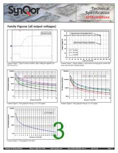
Application notes Figures A & B
Average PCB Temperature
5
10
125
10
V
kΩ
°C
°C
6
6
6
3.9
3.5
10 Hrs. Tb = 70°C
10 Hrs. Tb = 70°C
10 Hrs. See our website for details
Note 1: Start-up guaranteed above 10.3V, but will operate down to 9V
Note 2: Higher values of isolation capacitance can be added external to the module.
Note 3: Maximum value is 400ms for DC current limit and short circuit fault conditions
Product # IQ18xxxSKxxx
Phone 1-888-567-9596
www.synqor.com
Doc.# 005-0005462 Rev. C
05/27/10
Page 2

 SYNQOR [ SYNQOR WORLDWIDE HEADQUARTERS ]