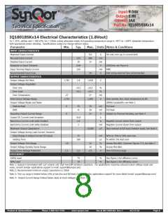
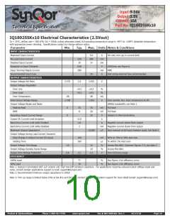
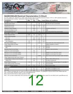
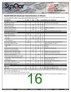
Input:9-36V
Output:3.3V
Current:8A
Part No.:IQ18033SKx08
Technical Specification
IQ18033SKx08 Electrical Characteristics (3.3Vout)
Ta = 25°C, airflow rate = 300 LFM, Vin = 18Vdc unless otherwise noted; full operating temperature range is -40°C to +100°C baseplate temperature
with appropriate power derating. Specifications subject to change without notice.
Parameter
Min.
Typ.
Max. Units Notes & Conditions
INPUT CHARACTERISTICS
Maximum Input Current
No-Load Input Current
5.0
250
14
A
mA
mA
V
Vin min; trim up; in current limit
200
10
Disabled Input Current
Response to Input Transient
Input Terminal Ripple Current
Recommended Input Fuse
OUTPUT CHARACTERISTICS
Output Voltage Set Point
Output Voltage Regulation
Over Line
0.05
240
250V/ms; see Figure 6
RMS
mA
A
20
Fast acting external fuse recommended
3.267
3.3
3.333
V
±0.1
±0.1
±0.3
±0.3
50
%
%
mV
V
Over Load
Over Temperature
-50
Total Output Voltage Range
Output Voltage Ripple and Noise
Peak-to-Peak
3.218
3.383
Over sample, line, load, temperature & life
20MHz bandwidth; see Note 1
Full load
0
0
25
5
50
10
8
mV
mV
A
RMS
Full load
Operating Output Current Range
Output DC Current-Limit Inception
Back-Drive Current Limit while Enabled
Back-Drive Current Limit while Disabled
Maximum Output Capacitance
Output Voltage during Load Current Transient
Step Change in Output Current (0.1A/µs)
Settling Time
Subject to thermal derating
9.6
3.3
2
A
A
Negative current drawn from output
mA
µF
Negative current drawn from output
10,000
Vout nominal at full load (resistive load); See Note 2
175
80
mV
µs
%
%
V
50% to 75% to 50% Iout max
To within 1% Vout nom
Output Voltage Trim Range
Output Voltage Remote Sense Range
Output Over-Voltage Protection
EFFICIENCY
-10
3.9
10
10
Across Pins 8&4; Common Figures 3-5; see Note 3
Across Pins 8&4
4.1
4.5
Over full temp range
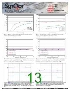
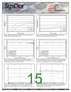
100% Load
81
80
%
%
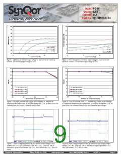
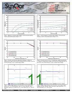
See Figure 1 for efficiency curve
See Figure 1 for efficiency curve
50% Load
Note 1: Output is terminated with 1µF ceramic and 15µF low-ESR tantalum capacitors. For applications requiring reduced output voltage ripple and
noise, consult SynQor applications support (e-mail: support@synqor.com)
Note 2: Recommended minimum output capacitance is 100uF
Note 3: Trim-up range is limited below 10% at low line and full load. Contact SynQor applications support for more detail (email: support@synqor.com)
Product # IQ18xxxSKxxx
Phone 1-888-567-9596
www.synqor.com
Doc.# 005-0005462 Rev. C
05/27/10
Page 12

 SYNQOR [ SYNQOR WORLDWIDE HEADQUARTERS ]