SM59A16U1
8-Bit Micro-controller
64KB with ISP Flash
& 6K+256B RAM embedded
7. Timer 0 and Timer 1
The SM59A16U1 has three 16-bit timer/counter registers: Timer 0, Timer 1 and Timer 2. All can be configured for
counter or timer operations.
In timer mode, the Timer 0 register or Timer 1 register is incremented every 1/12/96 machine cycles, which means that
it counts up after every 1/12/96 periods of the clk signal. It‟s dependent on SFR(PFCON).
In counter mode, the register is incremented when the falling edge is observed at the corresponding input pin T0or T1.
Since it takes 2 machine cycles to recognize a 1-to-0 event, the maximum input count rate is 1/2 of the oscillator
frequency. There are no restrictions on the duty cycle, however to ensure proper recognition of 0 or 1 state, an input
should be stable for at least 1 machine cycle.
Four operating modes can be selected for Timer 0 and Timer 1. Two Special Function registers (TMOD and TCON) are
used to select the appropriate mode.
Mnemonic
Description
Dir.
Bit 7
Bit 6
Bit 5
Bit 4
Bit 3
Bit 2
Bit 1
Bit 0
RST
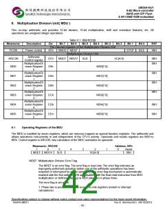
The relevant registers of Timer 0 and 1
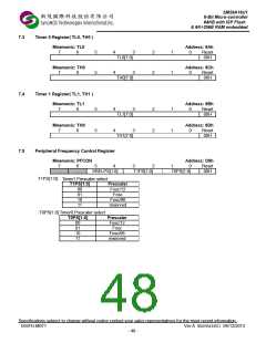
Peripheral
PFCON
Frequency control
register
D9h
--
SRELPS[1:0]
Timer 0 and 1
T1PS[1:0]
T0PS[1:0]
00H
TL0
TH0
TL1
TH1
TMOD
Timer 0 , low byte
Timer 0 , high byte
Timer 1 , low byte
Timer 1 , high byte
Timer Mode Control
Timer/Counter
8Ah
8Ch
8Bh
8Dh
89h
TL0[7:0]
00H
00H
00H
00H
00H
TH0[7:0]
TL1[7:0]
TH1[7:0]
GATE
TF1
C/T
M1
M0
GATE
C/T
IT1
M1
IE0
M0
IT0
TCON
88h
TR1
TF0
TR0
IE1
00H
Control
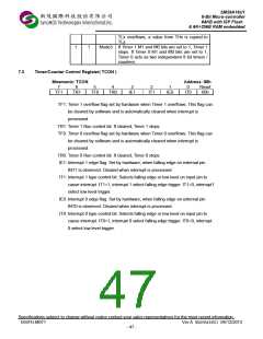
7.1
Timer/Counter Mode Vontrol Register (TMOD)
Mnemonic: TMOD
Address: 89h
7
6
C/T
5
M1
4
M0
3
2
C/T
1
M1
0
M0
Reset
00h
GATE
GATE
Timer 1
Timer 0
GATE: If set, enables external gate control (pin INT0 or INT1 for Counter 0 or 1,
respectively). When INT0 or INT1 is high, and TRx bit is set (see TCON
register), a counter is incremented every falling edge on T0 or T1 input pin
C/T: Selects Timer or Counter operation. When set to 1, a counter operation is
performed, when cleared to 0, the corresponding register will function as a
timer.
M1
M0
Mode
Function
0
0
Mode0 13-bit counter/timer, with 5 lower bits in TL0 or
TL1 register and 8 bits in TH0 or TH1 register
(for Timer 0 and Timer 1, respectively). The 3
high order bits of TL0 and TL1 are hold at zero.
Mode1 16-bit counter/timer.
Mode2 8 -bit auto-reload counter/timer. The reload
value is kept in TH0 or TH1, while TL0 or TL1
is incremented every machine cycle. When
0
1
1
0
Specifications subject to change without notice contact your sales representatives for the most recent information.
ISSFD-M071 Ver A SM59A16U1 04/12/2013
- 46 -

 SYNCMOS [ SYNCMOS TECHNOLOGIES,INC ]