LR8
Comparison with Discrete Startup Implementations
The LR8 provides several advantages when compared with discretely implemented start-up circuits.
Zener Implementation
Transistor Implementation
LR8 Implementation
LR8
VIN
VOUT
VIN
VOUT
VIN
VOUT
Disadvantages
•
Continues to draw current from high voltage source after
supply has bootstrapped, resulting in inefficiencies
Advantages
•
Bias must be set for minimum input voltage, resulting in
high current drain at high input voltages
•
LR8 goes into standby mode after supply has
bootstrapped, drawing no current from high voltage
input
•
•
•
•
Poor regulation
•
•
•
Good regulation
No current limit
Built-in current limiting
Overtemperature protection
No overtemperature protection
In the Zener implementation, requires large power resistor
and Zener
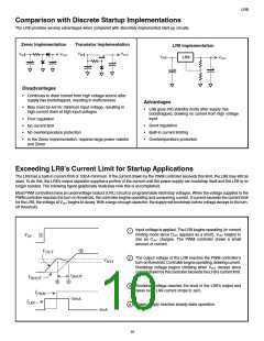
Exceeding LR8’s Current Limit for Startup Applications
The LR8 has a built-in current limit of 10mA minimum. If the current drawn by the PWM controller exceeds this limit, the LR8 may still be
used. To do this, the LR8’s output capacitor supplies a portion of the current until the power supply can bootstrap itself and the LR8 is no
longer needed. The following figure graphically illustrates how this is accomplished.
Most PWM controllers have an undervoltage lockout (UVL) circuit or programmable start/stop voltages. When the voltage supplied to the
PWM controller reaches the turn-on threshold, the controller begins operating and consuming current. If current exceeds the current limit
for the LR8, the voltage at VOUT begins to decay. With a large enough capacitor, the supply will bootstrap before voltage decays to the turn-
off threshold.
Input voltage is applied. The LR8 begins operating (in current
1
limiting mode since COUT appears as a short). VOUT begins to
rise as COUT charges. The PWM controller draws a small
amount of current.
1
V
IN
4
V
OUT
The output voltage of the LR8 reaches the PWM controller’s
turn-onthreshold.Controllerbeginsoperating,drawingcurrent.
Bootstrap voltage begins climbing while VOUT decays since
current drawn by the controller exceeds the LR8’s current limit.
2
V
HYS
t
BOOT
V
BOOT
3
2
Bootstrap voltage reaches the level of the LR8’s output and
takes over. LR8 current drops to zero.
3
4
I
PWM
10mA
I
LR8
Power supply reaches steady-state operation.
0mA
10

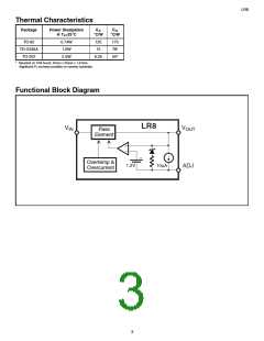
 SUPERTEX [ Supertex, Inc ]