Electrical characteristics
STM8S903K3 STM8S903F3
(3) To calculate PDmax(TA), use the formula PDmax = (TJmax - TA)/ΘJA (see Thermal characteristics).
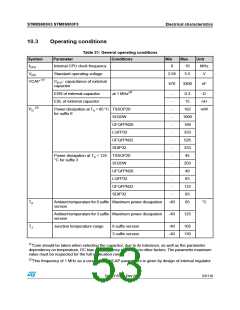
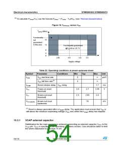
Figure 10: fCPUmax versus VDD
f
(MHz)
CPU
Functionality
16
12
8
not
guaranteed
in this area
Functionality guaranteed
@T -40 to 125 °C
A
4
0
4.0
Supply voltage
2.95
5.0
5.5
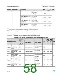
Table 22: Operating conditions at power-up/power-down
Symbol
Parameter
Conditions
Min
Typ
Max
Unit
tVDD
VDD rise time rate
2
∞
µs/V
VDD fall time rate(1)
2
∞
tTEMP
VIT+
Reset release delay VDD rising
1.7
ms
V
Power-on reset
threshold
2.6
2.5
2.7
2.65
70
2.85
VIT-
Brown-out reset
threshold
2.8
VHYS(BOR) Brown-out reset
hysteresis
mV
(1) Reset is always generated after a tTEMP delay. The application must ensure that VDD is
still above the minimum ooperating voltage (VDD min) when the tTEMP delay has elapsed.
10.3.1
VCAP external capacitor
Stabilization for the main regulator is achieved connecting an external capacitor CEXT to the
VCAP pin. CEXT is specified in the Operating conditions section. Care should be taken to limit
the series inductance to less than 15 nH.
54/116
DocID15590 Rev 8

 STMICROELECTRONICS [ ST ]