STM8S903K3 STM8S903F3
Package information
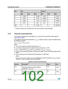
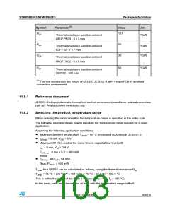
Symbol
Parameter(1)
Value
Unit
ΘJA
101
Thermal resistance junction-ambient
UFQFPN20 - 3 x 3 mm
°C/W
ΘJA
60
Thermal resistance junction-ambient
LQFP32 - 7 x 7 mm
°C/W
°C/W
ΘJA
38
Thermal resistance junction-ambient
UFQFPN32 - 5 x 5 mm
ΘJA
60
°C/W
Thermal resistance junction-ambient
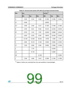
SDIP32 - 400 mils
(1) Thermal resistances are based on JEDEC JESD51-2 with 4-layer PCB in a natural
convection environment.
11.8.1
11.8.2
Reference document
JESD51-2 integrated circuits thermal test method environment conditions - natural convection
(still air). Available from www.jedec.org.
Selecting the product temperature range
When ordering the microcontroller, the temperature range is specified in the order code.
The following example shows how to calculate the temperature range needed for a given
application.
Assuming the following application conditions:
Maximum ambient temperature TAmax= 75 °C (measured according to JESD51-2)
•
IDDmax = 8 mA, VDD = 5 V
•
Maximum 20 I/Os used at the same time in output at low level with
•
IOL = 8 mA, VOL= 0.4 V
PINTmax = 8 mA x 5 V = 400 mW
Amax
PDmax = 400 mW + 64 mW
•
Thus: PDmax = 464 mW
TJmax for LQFP32 can be calculated as follows, using the thermal resistance ΘJA:
TJmax = 75 °C + (60 °C/W x 464 mW) = 75 °C + 27.8 °C = 102.8 °C
This is within the range of the suffix 6 version parts (-40 < TJ < 105 °C).
In this case, parts must be ordered at least with the temperature range suffix 6.
DocID15590 Rev 8
103/116

 STMICROELECTRONICS [ ST ]